Removal of Impulse Switch
Renewing Impulse Switch on Wiper Motor
Removal
1 Remove wiper motor. Remove/Install Wiper Motor
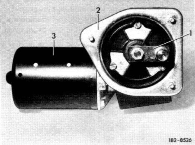
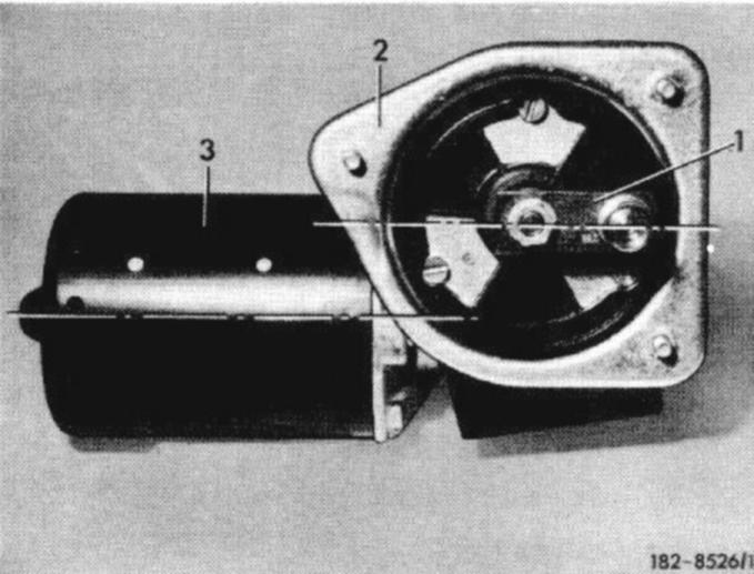
2 Mark crank position in relation to shaft, loosen hex. nut and remove crank (1).
3 Unscrew screws of fastening plate (2) and remove fastening plate.
4 Unscrew angle bracket with impulse switch and plug connection.
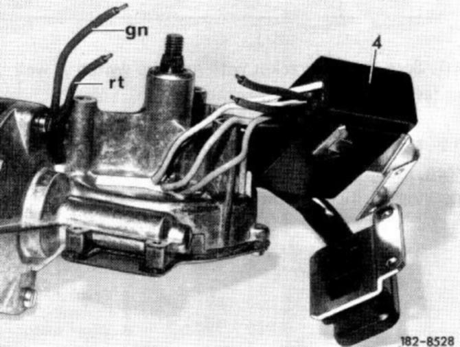
5 Seperate green and red lines leading into wiper motor, strip ends and tin.
4 Impulse switch
gn Green
rt red
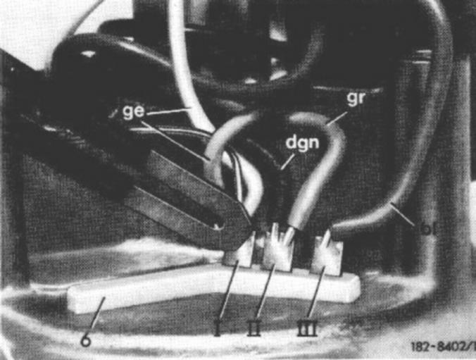
6 Unsolder yellow, gray and blue lines from soldering lugs of insulating part.
7 Cut red and green lines ("B and D") of new impulse switch to approx. 70 mm length: strip ends and tin.
6 Insulating part
I Soldering Lug - yellow lines and grounding wire
II Soldering Lug - grey and dark green line
III Soldering Lug - blue line
8 Slip on insulating hose each 40 mm long over red and green lines leading into wiper motor. Then insert these lines into one soldering sleeve each (tubular rivets A3 x 0.25 x 10, DIN 7340 MS) and solder to respective lines "B" and "D" of impulse switch. Then slip insulation hoses over soldering sleeve.
9 Solder yellow, grey and blue lines of impulse switch to soldering lugs. Make sure that the ground connecting wire is additionally soldered to soldering lug I and the dark green line additionally to soldering lug II.
Installation
10 Screw angle bracket with impulse switch as well as fastening plate to wiper motor.
11 If mark of former crank position can still be seen, mount crank accordingly. If not, run motor into parking position, adjust crank and screw down.
Testing Wiper Motor Prior to Installation
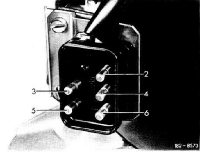
12 Connect a positive and a negative line to a 12-volt battery. Clamp positive line to plug pin No. 3, negative line to plug pin No. 6.
Connect an additional line to positive pole of battery and hold other end of this line against plug pins No. 2,4 and 5 one after the other.
Plug pin No.2: connection for slow
Plug pin No 4: connection for fast
Plug pin No 5: connection for interval