Mounting Crankshaft In Bearings
NOTE: This procedure is for an engine that is removed and disassembled
NOTE: Self-locking stud bolts are screwed into the crankcase for mounting the crankshaft bearing caps.
These stud bolts must Only be screwed in once as the locking adhesive applied over about 8 mm of the length of the thread is no longer effective once the stud is unscrewed again.
When replacing the stud bolts, pay attention to the different insertion depth and collar dia.
When performing repairs, Heli-Coil inserts must not be used for the self-locking stud bolts of the crankshaft bearing caps.
As of November 1984 the holes for the stud bolts in the bearing caps are provided with a turned face. At the same time the collar of the stud bolts was modified from 12.8 mm dia. to 14.8 mm dia.
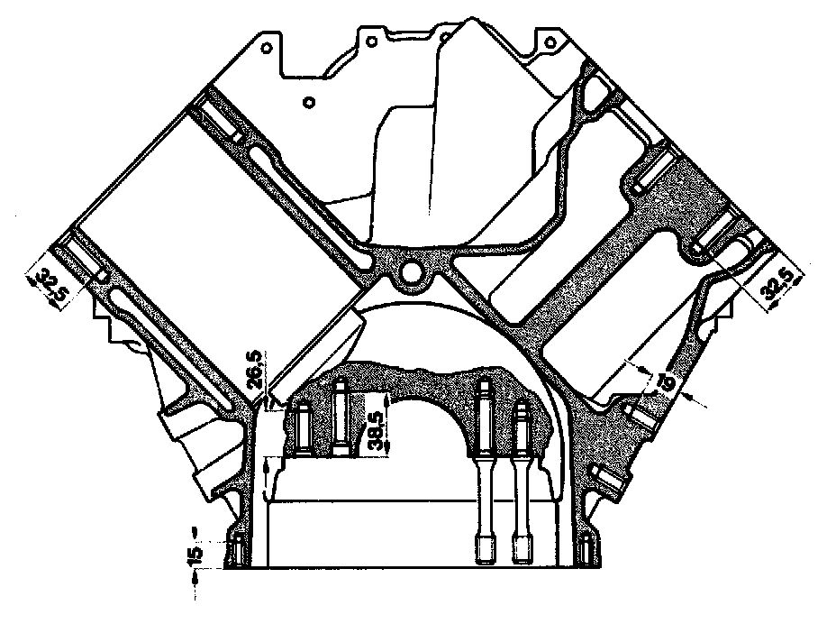
The 5 crankshaft bearing caps of chilled cast iron are fitted into the side of the crankcase with an overlap of 0.01 mm.
The three middle bearing caps are additionally bolted to the side walls of the crankcase.
The crankshaft bearing caps are machined together with the crankcase and are not available as a replacement part.
Mount crankshaft in bearings with the engine removed and disassembled.
Following damage to a bearing, the conrods must be removed and any swarf in the conrod bores removed.
Carefully clean the oil ducts in the crankcase, crankshaft, timing case cover, oil filter housing, closing cover, oil pump etc.
Examine crankshaft for cracks, dimensional tolerance and hardness. Checking and Reconditioning Crankshaft
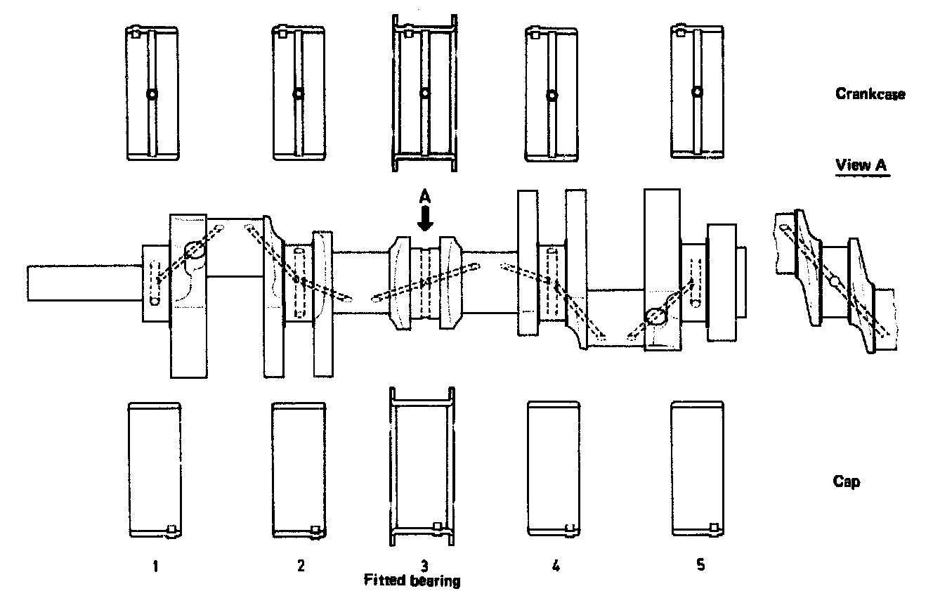
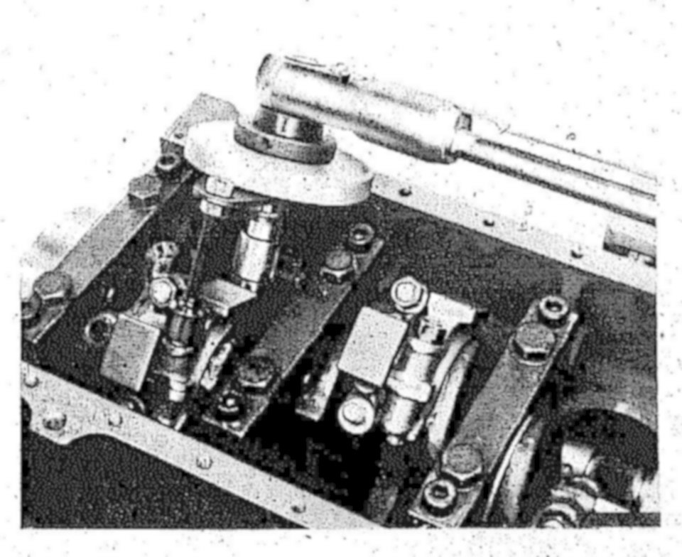
Associating crankshaft bearings, installing crankshaft
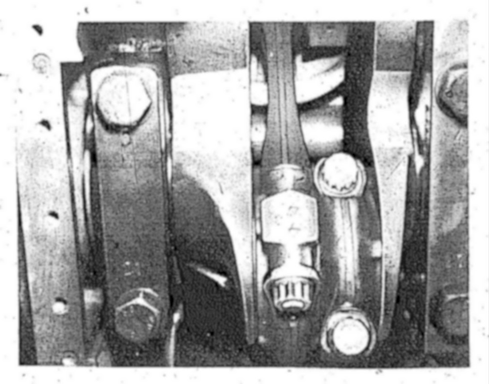
1 Install crankshaft bearing cap, observe marks, 1 is at the front
The bearing caps are fitted asymmetrically, in this way the caps can only be installed in one position.
2 Lubricate nut contact area and threads, tighten nuts with 50 Nm.
3 Lubricate thread and bolt head contact area of lateral bolts (M 10x 40), install with washers and tighten with 50 Nm.
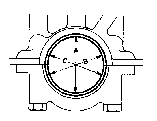
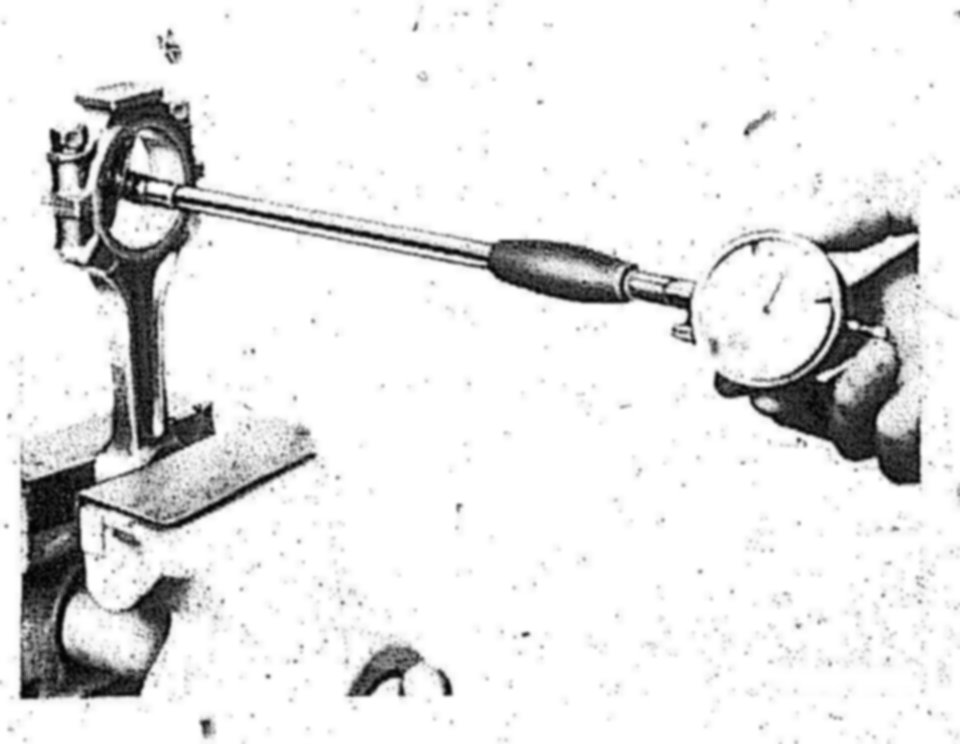
4 Measure basic bore in direction A. B and C at two levels (conicity). Note down values.
With the basic bore which exceeds the specified value or is conical, touch up bearing cap contact surface on a surface plate to a maximum of 0.02 mm.
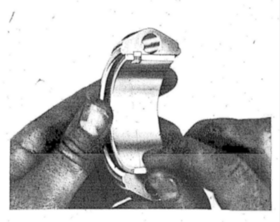
5 Insert bearing shells, mount crankshaft bearing caps.
Tighten nuts to 50 Nm and lateral bolts with 50 Nm.
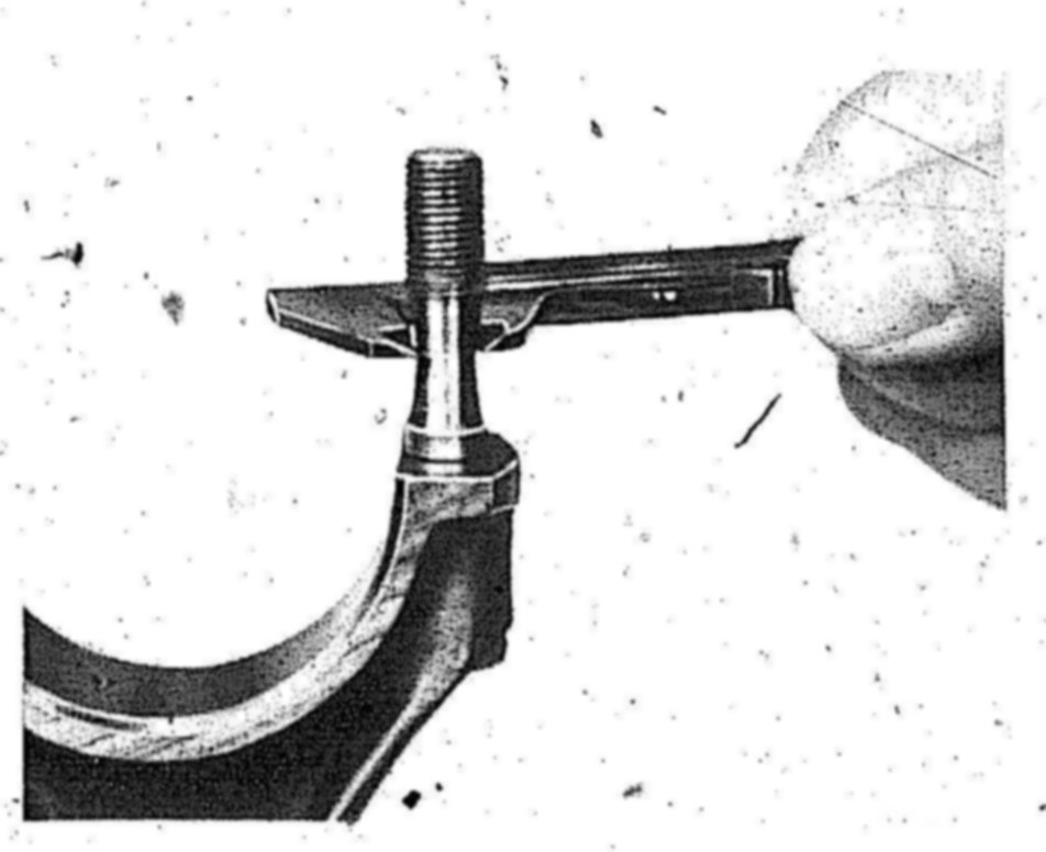
6 Measure bearing diameter, note down measured values.
7 Measure crankshaft journal, then determine crank- shaft radial bearing play.
NOTE: The bearing play can be corrected by using different bearing shells, while the aim should be for the mean value of the specified bearing play. Crankshaft bearing shells without color coding are thicker than the ones with blue color coding. It must be observed however that the wall thicknesses of shells without and with color coding may overlap.
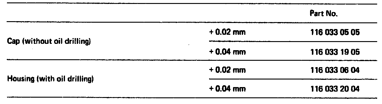
Bearing shells with a larger wall thickness are available for reducing the radial crankshaft bearing play with standard size:
Bearings 1, 2, 4, 5:
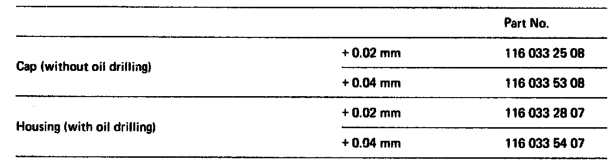
Fit Bearings:
8 Measure width of fitted bearing journal and the fitted bearing. Determine crankshaft axial bearing play.
The fitted bearing shells of the repair stages are available in oversize.
Both fitted bearing shells must be machined together on both sides to the width of the fitted bearing journal minus the axial play.
9 Coat bearing shells and crankshaft with engine oil SAE 30 and fit crankshaft.
CAUTION: Do not use bearing shells without oil hole in the crankcase but only in the bearing cap.
Tightening Diagram:
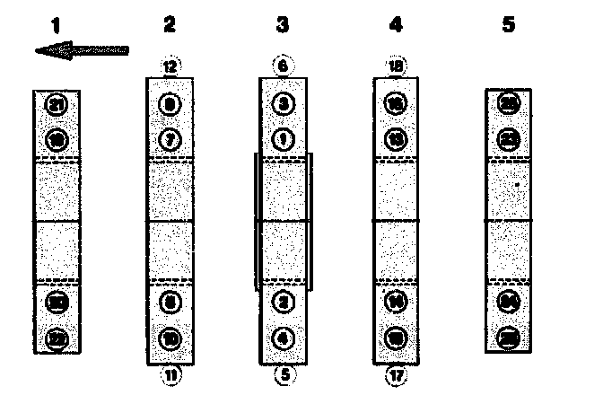
10 Tighten crankshaft bearing caps to the specified torque in the order of the tightening diagram. Oil the thread and the bolt head or nut contact surface for this step.
Nuts 50 Nm.
Side bolts 50 Nm.
NOTE: Bolts of quality 10.9 should be used for the side bearing cap bolts. From November until December 1984, crankcases without side bolts for the crank shaft bearing caps 2.3 and 4 and without side holes for these bolts were installed.
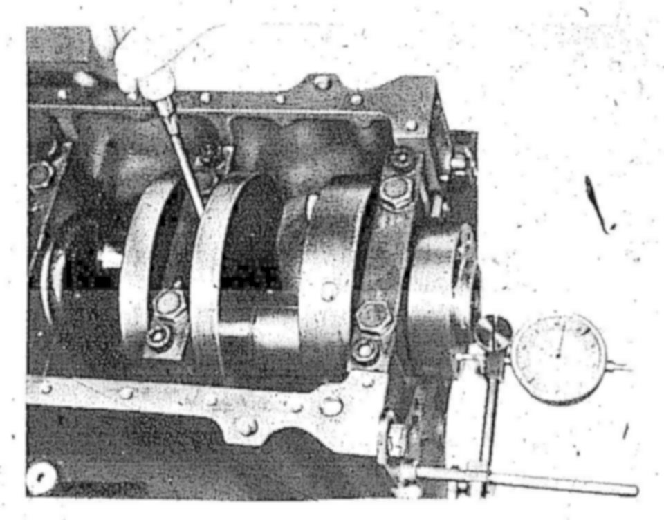
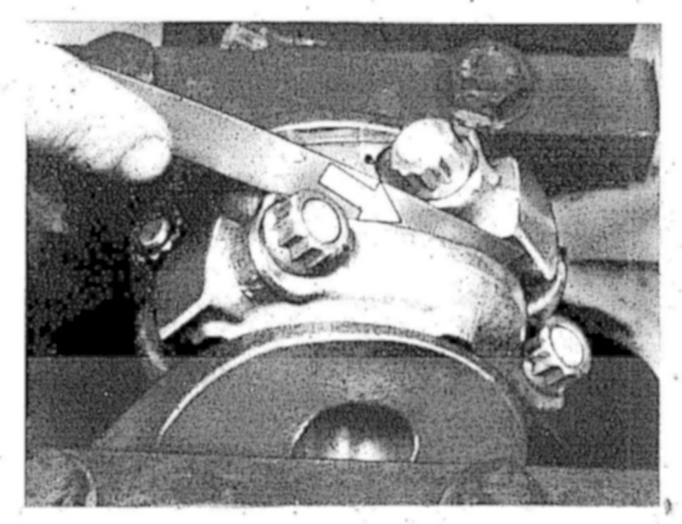
11 Measure axial crankshaft bearing play.
12 Turn crankshaft by hand and check whether it runs freely.
Associating Connecting Rod Bearings and Installing Connecting Rods:
13 Check connecting rod (conrod) bolts.
14 Recondition and square connecting rods. Service and Repair
15 Matching the stamped numbers, mount connecting rod bearing caps. Tighten connecting rod nuts with 40 - 50 Nm.
16 Measure basic bore in two directions. If the basic bore exceeds the specified value or is conical, touch up bearing cap contact surface on a surface plate up to a maximum of 0.02 mm.
17 Insert connecting rod bearing shells, install connecting rod bearing caps with bearing shells and tighten connecting rod nuts with 40 - 50 Nm.
18 Measure and note bearing diameter.
19 Measure crank pin. Determine radial connecting rod bearing play.
NOTE: The bearing play can be corrected by using different bearing shells, while the aim should be for the mean value of the specified bearing play. Crankshaft bearing shells without color coding are thicker than the ones with blue color coding. It must be observed however that the wall thicknesses of shells without and with color coding may overlap.
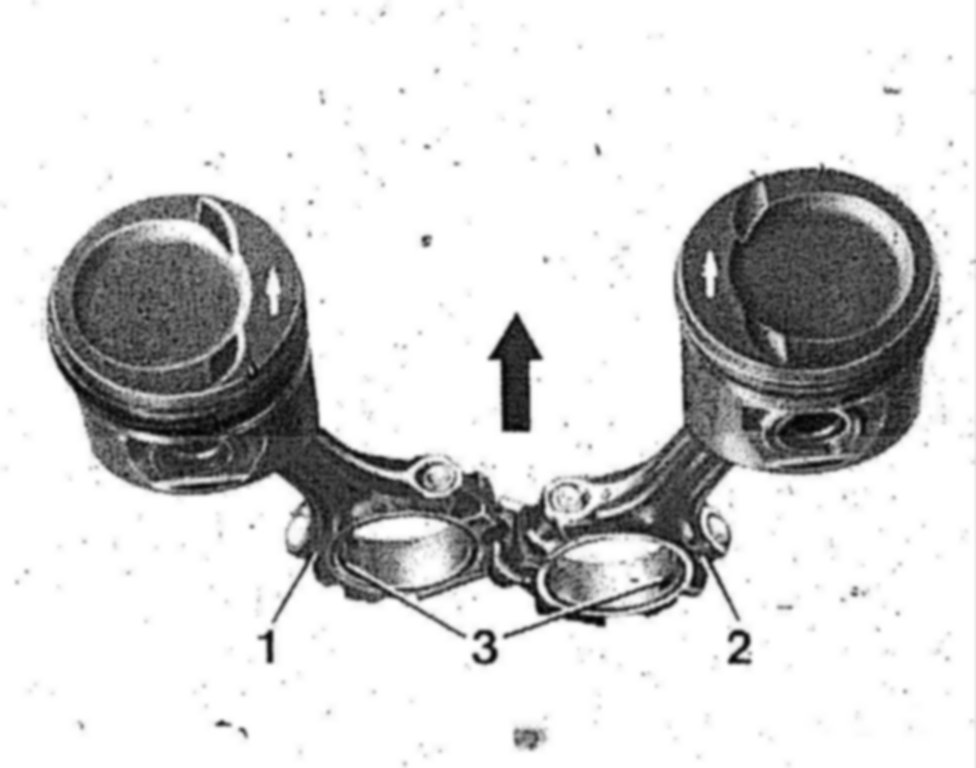
1 Connecting rod contact side
3 Locating grooves for bearing shells
20 Mount piston and connecting rods. Service and Repair
To do so, use cover sleeves on connecting rods to prevent damage to the cylinder wall.
21 Lubricate bearing shells, crankshaft, pistons and cylinders with engine oil SAE 30. Install connecting rods with pistons. Service and Repair
Observe marking!
22 Tighten connecting rod nuts with 40 - 50 Nm initial torque and 90 - 100° angle of rotation torque.
23 Measure axial connecting rod bearing play. Ensure freedom of movement of connecting rods in the pistons.
CAUTION: Disassemble oil pump, clean and renew if required. Renew oil pressure limiting valve. Disassemble oil filter upper part and clean, carefully clean air-oil cooler or renew. Unscrew and clean oil pressure relief valve for oil filter insert and oil cooler bypass valve. Disassemble and clean oil damper.
Fit initial operation oil filter insert After 1000 to 1500 km, change engine oil and oil filter element
NOTE: When performing repairs, the 1st version of crankshaft can be installed in model 107.028 with engine 117.960 in place of the shorter crankshaft 117 031 14 01 together with an additional longitudinal compensating washer (10.5 mm thick) and the longer stretch bolts (29 mm instead of 23 mm) (see Removing and Installing Driven Plates [flex plate/fly wheel]).
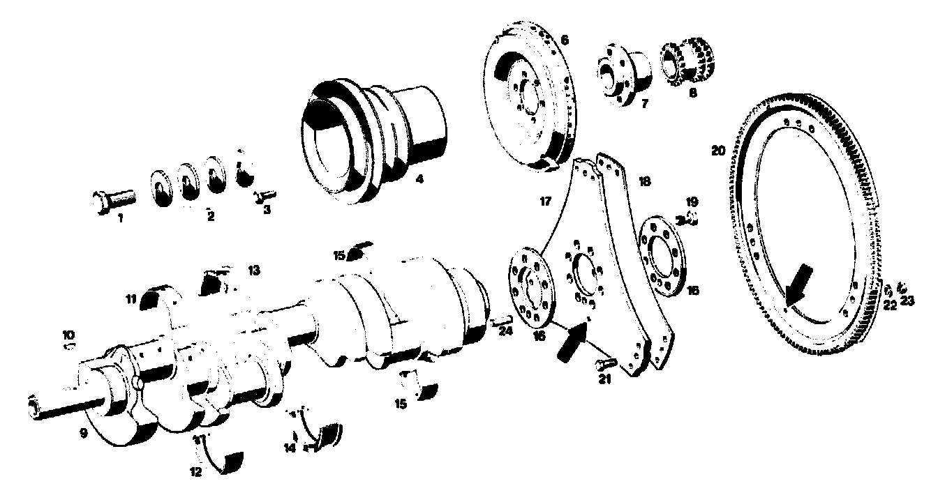
1 Bolt M 18 x 1.5 x 45
2 Diaphragm springs (4 required), 2nd version
3 Bolt M 8 x 22 (6 required)
4 V-belt pulley
6 Vibration damper
7 Hub
8 Crankshaft sprocket
9 Crankshaft
10 Woodruff key
11 Crankshaft bearing shell in crankcase
12 Crankshaft bearing shell in bearing cap
13 Fitted bearing shell in crankcase
14 Fitted bearing shell in bearing cap
15 Connecting rod bearing shells
16 Plates 4.5 mm thick
17 Driven plate 1.5 mm thick, 296 mm die.
18 Driven plate 1 mm thick. 287 mm die.
19 Necked-down bolt for driven plates M 12 x 1.5 x 23 (8 required)
20 Ring gear with segments
21 Fitted bolts
22 Spring washer B 6
23 Nut M 6
24 Dowel pin (only for EZL transmitter)