A/T - Delayed/Harsh Engagement 'D' to 'R'
88MERCEDES07DATE: May 1990 (supersedes MBNA 27/10b, Nov. 89) REF. NO. 27/10C
SUBJECT: HARD TRANSMISSION ENGAGEMENT WHEN GEAR SELECTOR IS SHIFTED QUICKLY FROM "D" TO "R" MODELS WITH LIGHT ALLOY V-8 ENGINES 116/117 As OF M.Y. 1984, AUTOMATIC TRANSMISSION W4A 040 (722.3)
Note: This update includes the addition of paragraph three. Please discard MBNA 27/10a and replace with MBA 27/10c - retain the Work Instructions No. 189a.
As of October 1987, a Belleville washer is installed in the multiple disc brake LB3 to resolve complaints of hard transmission engagement when the gear selector is shifted quickly frcm "D" to "R".
Effective Serial
Transmission Transmission End No.
722.3 3012800
Transmissions prior to production phase-in may be modified according to the work procedure described in the service microfiche Automatic Transmission 722.3.
Prior to doing any repair work, try to resolve custcmer complaints about hard transmission engagement when shifting quickly from "D" to "R" by replacing transmission fluid with ATF, part no. 001 989 07 03 (this oil should not be used for regular maintenance on vehicles with no complaints). The vehicle should then be reevaluated after having been driven to to 300 miles. If the complaint is not resolved after this period, then certain transmission components should be replaced.
A brief description of the procedure listing modified parts, replacement parts, their respective part numbers and job numbers, can be found in the attached Work Instruction No. 189a.
Note: If transmission ccmponents were replaced, the ATF, part no. 001 989 07 03 must not be used. Always use regular ATF according to the current Service Information "Factory-Approved Service Products".
No. 189a
Date: November 1988 (supersedes W.I.189 Grp.27, Jan. 1988) Grp.27
Subject: HARD TRANSMISSION ENGAGEMENT WHEN GEAR SELECTOR IS SHIFTED QUICKLY FROM "D" TO "R" MODLES WITH LIGHT ALLOY V-8 ENGINES 116/117 AS OF M.Y. 1984, AUTOMATIC TRANSMISSION W4A 040 (722.3)
Transmissicns prior to production phase-in may be modified according to the work procedure described in the service microfiche Automatic Transmission 722.3. A brief description of the procedure listing modified parts, replacement parts, their respective part numbers and job numbers follows.
The following parts must be replaced or modified:
- Valve body (shift valve housing)
- Large intermediate plate
- Gasket for large intermediate plate
- Return springs for reverse gear piston
- Compensating washer for multiple disc brake LB3
- Steel plates for multiple disc brake LB3
- Gasket for lower cover
- Front cover (rebore oil inlet hole)
- Band 2 replacement requires prior zone authorization (Job no. 27 - 640 covering B2 replacement)
Note: Only in case of customer complaint when shifting quickly from "R" to "D".
Procedure
1. Remove transmission, see job no. 600.
2. Remove front cover of primary pump, see job no. 630.
3. Remove reverse gear piston.
Note: Reverse gear piston should not be provided with a check valve (part of a previous modification).
4. Remove fastening screw for primary pump. Completely re-drill inlet bore in front cover to 7 mm dia., then thorougly clean out bore with compressed air. Reinsert screw and tighten.
Tightening Torque: 20 N-m.
5. Insert reverse gear piston LB3 with 20 new return springs. To do so, use special tools 201 589 12 43 00 and 126 589 04 14 00.
FIGURE 1:
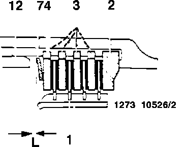
6. Remove clutch pack LB3. Assemble new steel plates (2, 3, 4) with existing friction plates (Figure 1).
Note: The steel plate (4) must always have a thickness of 2.8 ma. The plates (3) can vary within the specified release clearance. Steel plates are available in thicknesses of 2.3 and 2.8 mm.
7. Insert clutch pack and Belleville washer (7) according to Figure 2.
8. Check release clearance (L = 1.5 - 2.0 mm) with special tool 126 589 04 31 00 and compensate, if necessary, using steel plates (3) of suitable thickness (Figure 1).
9. Remove valve body (shift valve housing) and brake band piston B2.
10. Check free-play of brake band B2 and adjust, if necessary.
Nominal value: 5.5 - 6.0 mm. Check free-play of brake band B1 and adjust, if necessary. Nominal value:
1.8 - 2.8 mm. (see Service Information 27/77, December 1986 regarding modifications to B1 and Service Microfiche for additional information regarding Special Tools)
1 Friction plates
2 End plate
3 Steel plates, 2.3 or 2.8 mm thick
4 Steel plate, 2.8 mm thick
7 Belleville washer
12 Reverse gear piston
FIGURE 2:
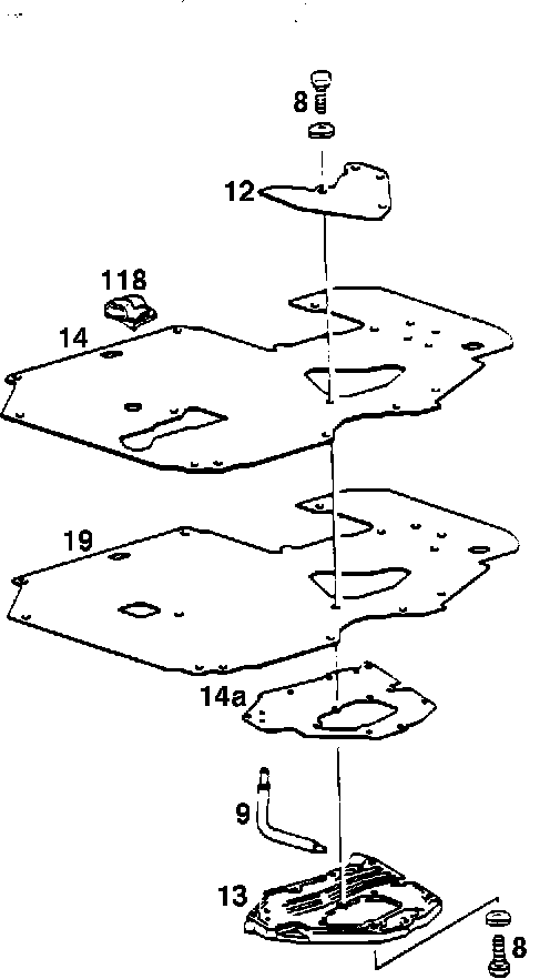
11. Remove lower cover of valve body (13), see job no. 430 (Figure 2).
12. Disassemble lower cover, replace large intermediate plate (19) and gasket (14), and install additional gasket (14a), see job no. 435 (Figure 2).
13. Install lower cover and new valve body.
Tightening Torque: 8 N-m
14. Change the stamped-in part number on the transmissionb housing as follows:
Model Previous Part Number Modified Part Number
107.045 107 270 25 01 107 270 55 01
107.048 126 270 77 01 107 270 53 01
126.032 126 270 46 01 126 270 07 00
126.035 126 270 74 01 126 270 05 00
126.037/044 126 270 49 01 126 270 08 00
126.039/045 126 270 76 01 126 270 04 00
Parts Information
Qty. Part Name Model
Part
1 Valve body
380 SE (126.0 2) 126 270 24 71
380 SL (107.045)
1 Valve body
500 SEL/SEC (126.037/044) 126 270 25 71
1 Valve body 420 SEL (126.035)
126 270 21 71
1 Valve body
560 SEL/SEC (126.039/045) 126 270 20 71
560 SL (107.048)
1 Intermediate plate All models
126 277 08 15
1 Gasket (1) (valve body)
All models except 560SEL/SL 126 277 07 80
1 Gasket (2) (lower cover gasket) All models
126 277 08 80
1 Gasket (3) (valve body)
560 SEL/SEC (126.039/045) 126 277 09 80
560 SL (107.048)
1 Belleville washer
126 993 18 26
20 Return springs
126 993 27 02
3 Steel plates (2.3 mm thick) (4)
2 Steel plates (2.8 mm thick) (4) 126 272 67 26
1 End plate (7.7 mm thick) 126 272 68 26
1 Brake band piston B2 (5) 126 272 69 26
1 Brake band B2 (6) 107 270 00 32
126 270 14 62/05
The following parts are required for the adjustment of brake band B1:
1 Washer (0.5 mm)
000988 008015
1 Washer (1.0 mm)
000988 008006
1 Washer (1.5 mm)
000988 008024
The following parts are required for the adjustment of brake band B2:
1 Pin (48.0 mm)
126 277 72 75
1 Pin (48.8 mm)
126 277 73 75
1 Pin (49.6 mm)
126 277 74 75
(1) Phased into production as of transmission end no. 741 819.
(2) Phased into production as of transmission end no. 904 533.
(3) Vehicles with engine 117 Up to transmission end no. 126 277 07 80; as of transmission end no. 910 187, install gasket 126 277 09 80.
(4) Quantity varies, see note to step 6, page 2.
(5) Phased into production as of transmission end no. 909 454.
(6) Replacement of Band 2 (job no. 27-640) requires prior zone authorization
Special Tool Information
Tool Name Tool Number Group/Category Dealer Net Price*
Installation sleeve 126 589 04 14 00 27/C $ 99.52
Parallel bar 126 589 04 31 00 27/C $ 34.42
Assembly fixture 201 589 12 43 00 27/C $108.50
Measuring screw for 126 589 06 21 00 27/C $ 13.10
adjustment of brake band B1
Twist drill local purchase
(7 mm dia., 200 mm long)
* Subject to change
In Case of Warranty
Time Allowance
02-2737 Primary Pump Inlet Bore and 3.4 hrs. 11/15
Reverse Gear Piston, Modify (W.I. 189a) 51/54/55
71/72/73
02-2744 Brake Band B2, Repl. (W.I. 189a) 3.7 hrs. 11/15
(Transm. partially disassembled) 51/54/55
71/72/73
Damage Code
27001 62 - Transmission, hard engagement (use this damage code only if problem cannot be attributed to a specific transmission component).
27401 16 - Valve body, hard shifting
If problem is caused by a specific component, select appropriate damage code from Damage Code Manual or Microfiche.
Nots: Additional work performed on transmission must be coded accordingly.