Removal and Installation of Rear Propeller Shaft
REMOVAL AND INSTALLATION OF PROPELLER SHAFT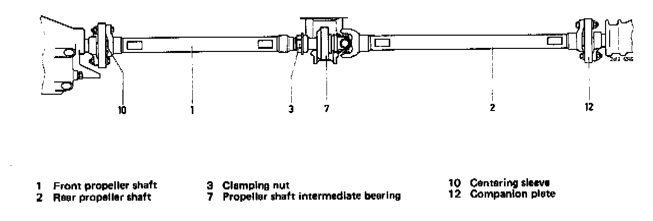
Removal
1 Remove exhaust system.
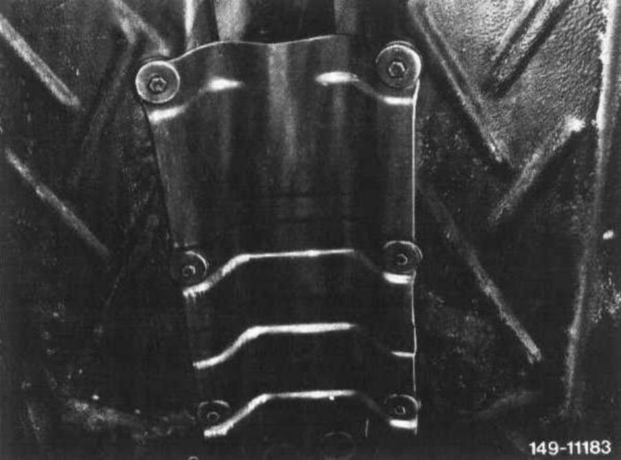
2 Unscrew shielding plate.
3 Lift transmission and jack up.
4 Loosen clamping nut of propeller shaft for about 2 turns without pushing back rubber sleeve (slides along).
Model 107:
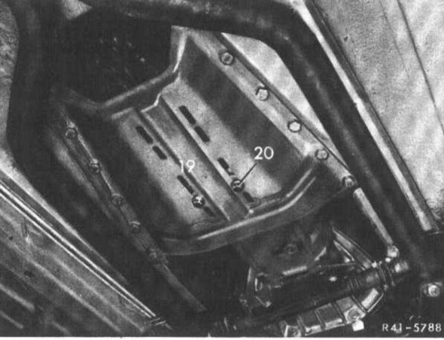
5 On model 107, unscrew hex bolts on tunnel closing plate (19) as well as the two screws (20) of the rear engine mount and remove tunnel closing plate (19).
Model 116:
6 On model 116, unscrew hex bolts of rear engine carrier on frame floor as well as those for rear engine mount and remove.
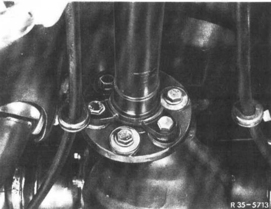
7 Unflange propeller shaft on transmission and on rear axle.
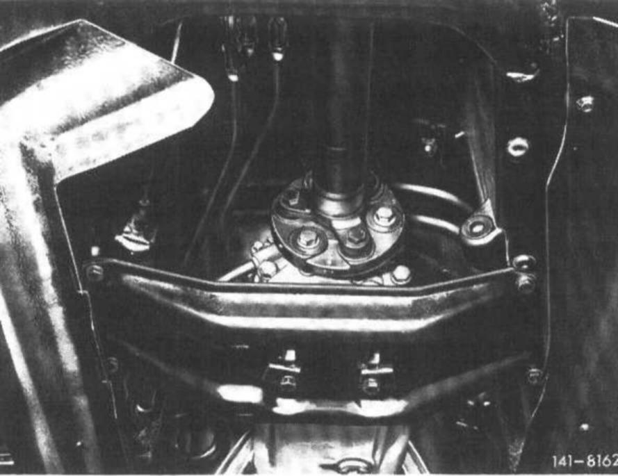
8 Unscrew hex bolts for attaching propeller shaft intermediate bearing to frame floor.
9 Disconnect compensating lever of parking brake.
10 Force propeller shaft from centering pin of rear axle drive pinion and pull out toward the rear. Make sure that the propeller shaft is not separated.
Attention! If the propeller shaft must be separated, mark all parts in relation to each other since the propeller shaft is balanced as a unit. On model 107.042 starting August 1982 the front and rear propeller shaft are pertinently identified.
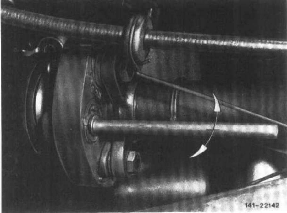
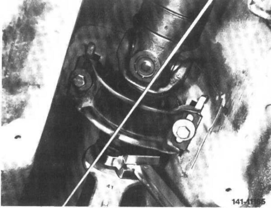
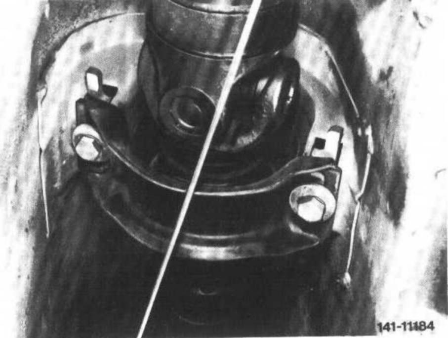
11 On models 107.022/042 starting September 1982 with radially or tangentially soft companion plates, the vulcanized centering bushings on companion plate must be loosened prior to sliding propeller shaft out of universal flange (arrows). For this purpose, use a cylindrical mandrel of 10 mm dia. and approx. 150 mm in length.
Note: Check companion plates, centering sleeves and propeller shaft intermediate bearing for damage, if any. Replace damaged parts.
Installation
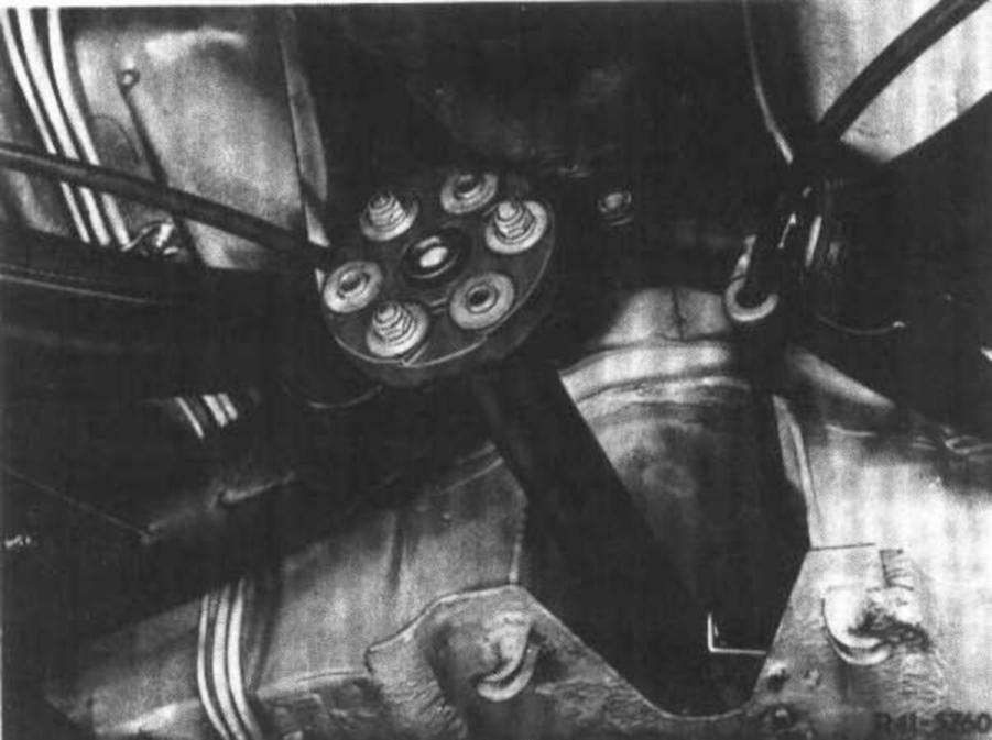
12 Fill cavities of the two centering sleeves with the specified grease (approx. 6 grams per sleeve).
13 Slide propeller shaft with companion plates on centering pins on transmission and on rear axle.
14 Attach propeller shaft intermediate bearing to frame floor, but do not yet tighten.
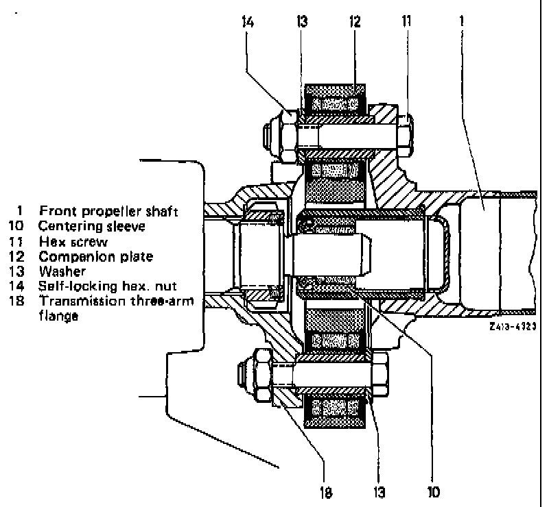
15 Attach propeller shaft to transmission into rear axle. Tightening torque of self-locking hex nuts (14) for M 10 = 45 Nm and for M 12 = 65 Nm.
Attention! Renew self-locking hex. nuts on principle.
Model 116:
16 Mount tunnel closing plate or rear engine carrier to frame floor, tightening torque of hex screws for M 8 = 25 Nm and for M 10 = 45 Nm.
Model 107:
17 Lower transmission, position hex screws (20) for rear engine mount and tighten to 25 Nm.
18 Tighten clamping nut on propeller shaft to 30-40 Nm, making sure of seating sleeve well.
19 Tighten hex bolts for attaching propeller shaft intermediate bearing to frame floor to 25 Nm.
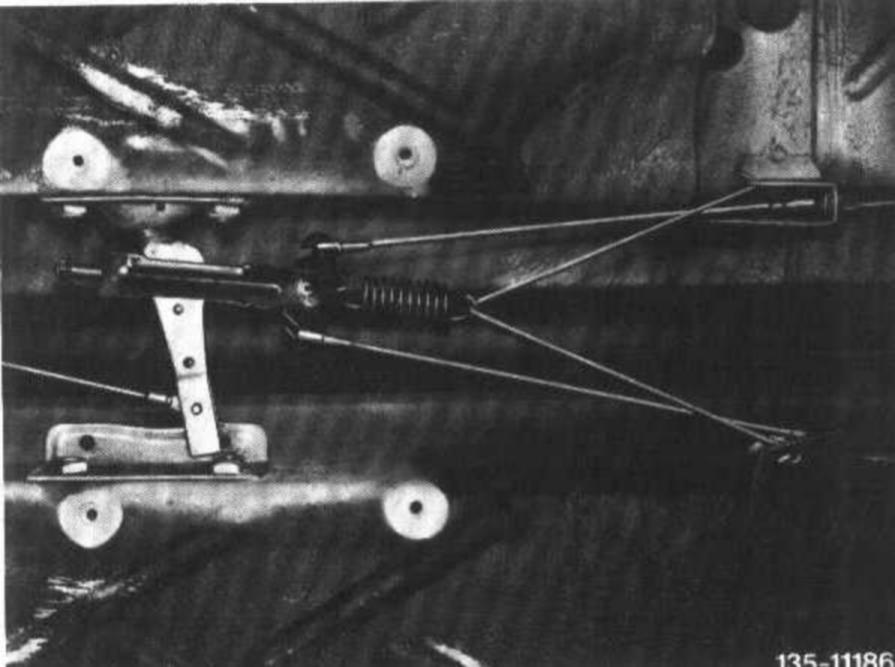
20 Attach compensating arm of parking brake.
21 Mount shielding plate.
22 Install exhaust system.