Propeller Shaft/Vibration Damper/Flexible Coupling
RENEWING CENTERING SLEEVENote: In the event of wear or damage of sealing lip of centering sleeve (10) of front or rear propeller shaft the complete propeller shaft need not be replaced, since the centering sleeve can be individually exchanged.
Removal
Remove propeller shaft.
On propeller shafts with vibration eliminator 1st version
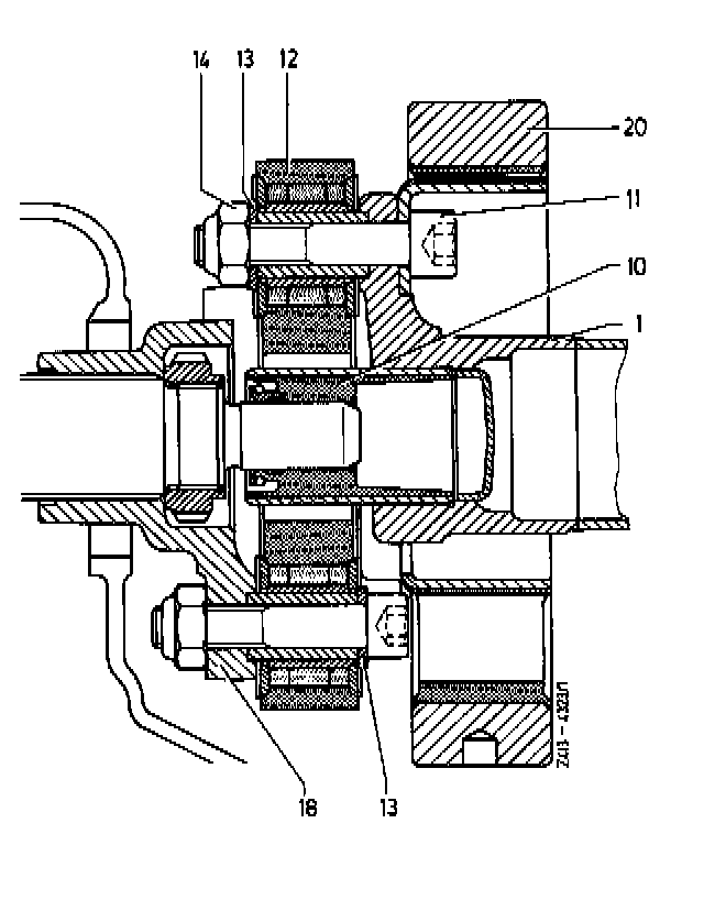
1 Unscrew hex. socket screws (11) with self-locking hex. nuts (14) and remove.
1 Front propeller shaft
10 Centering sleeve
11 Hex socket screw
12 Companion plate
13 Washer
14 Self-locking hex. nut
18 Transmission universal flange
20 Vibration eliminator
Attention! Prior to removing vibration eliminator (20), mark vibration eliminator and three-arm flange in relation to each other.
On propeller shafts with vibration eliminator 2nd version
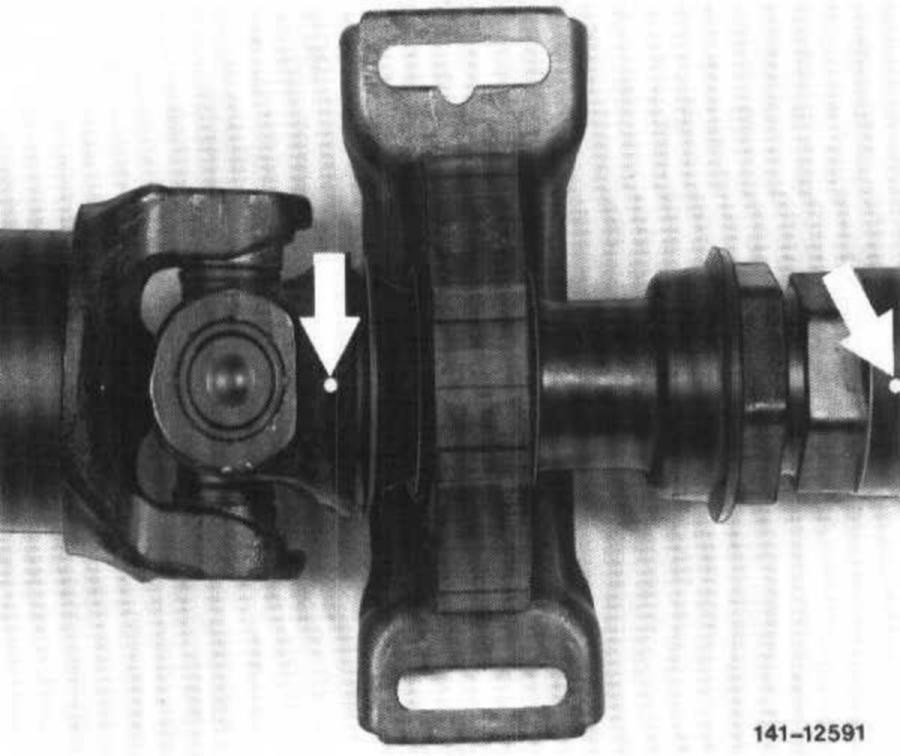
2 Unscrew hex. socket screws with self-locking hex. nuts and remove. On this version, an identification is located on three-arm flange (one hump) and on vibration eliminator (one vulcanized arrow).
3 Push back vibration eliminator (20) on front propeller shaft.
Propeller shafts without vibration eliminator:
4 Mark companion plate in relation to three-arm flange of propeller shaft and remove.
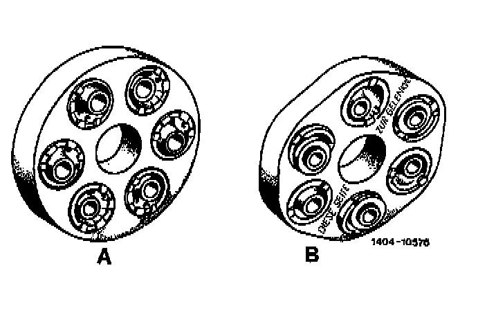
Attention! On radially or tangentially soft companion plates, loosen the vulcanized fitted sleeves in three-arm flange. For this purpose, use a cylindrical mandrel of 10 mm dia. and approx. 150 mm in length.
A = Radially soft companion plate
B = Tangentially soft companion plate
On Vehicles Starting August 1982:
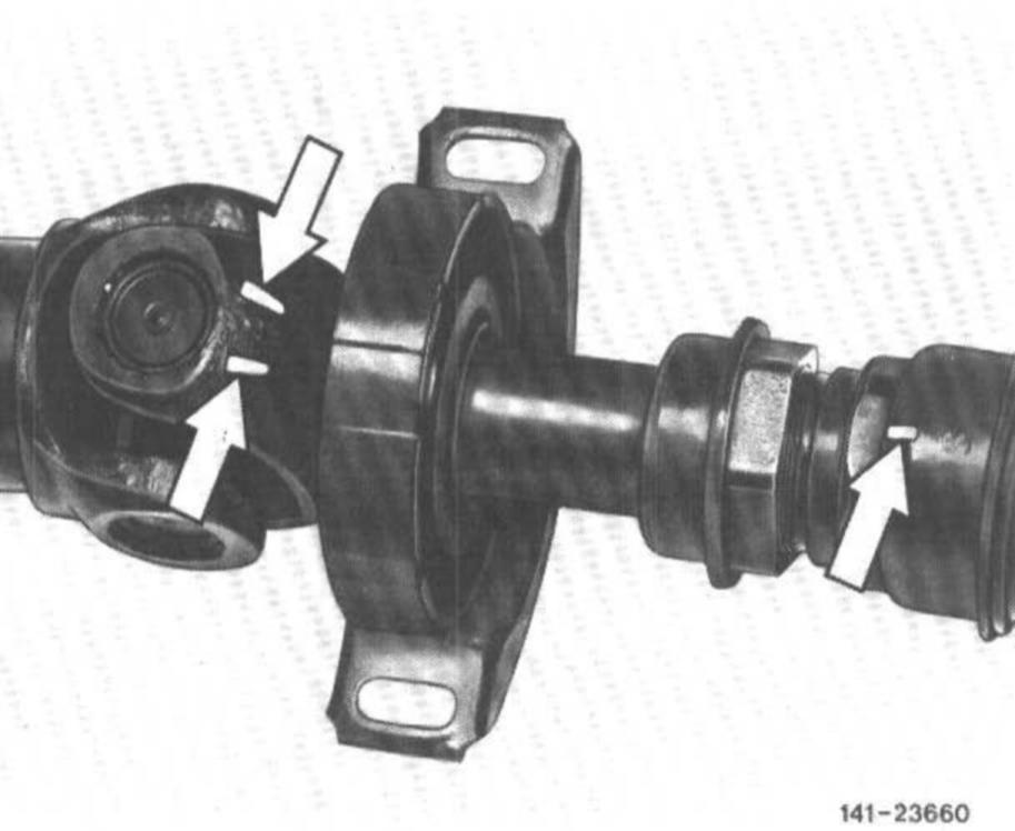
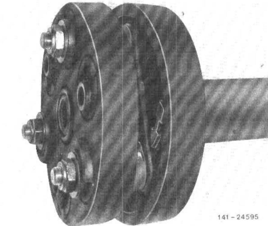
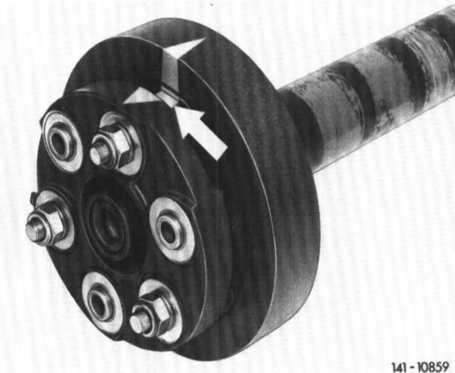
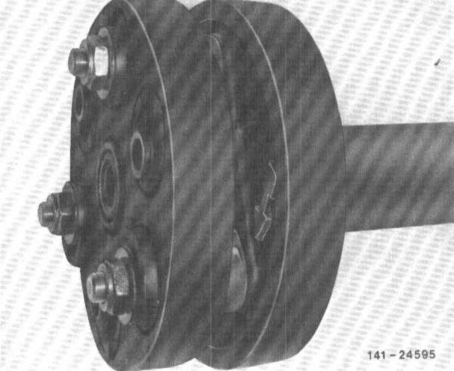
5 When separating front and rear propeller shaft, mark components in relation to each other (arrows).
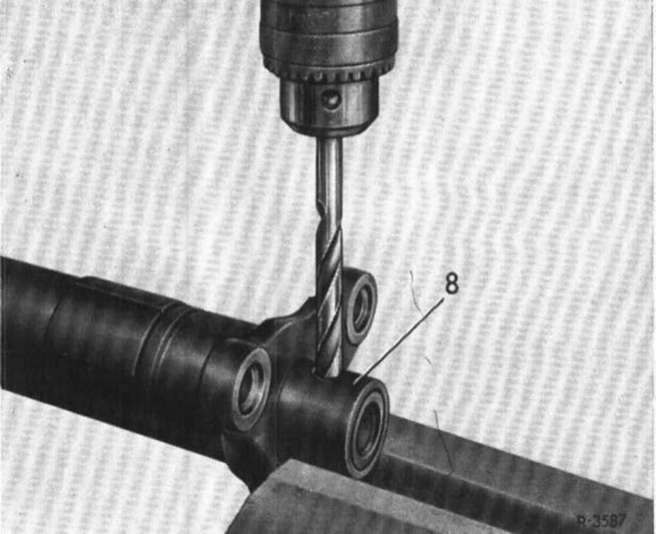
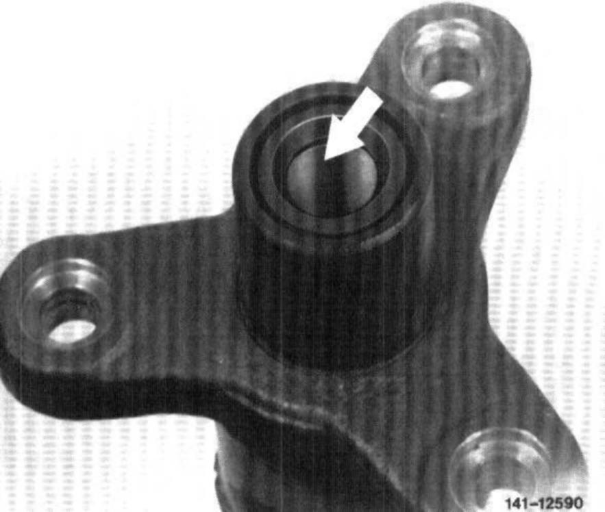
6 Drill a hole of approx. 10 mm dia. at right angles through sleeve approx. 15 mm from face of centering sleeve.
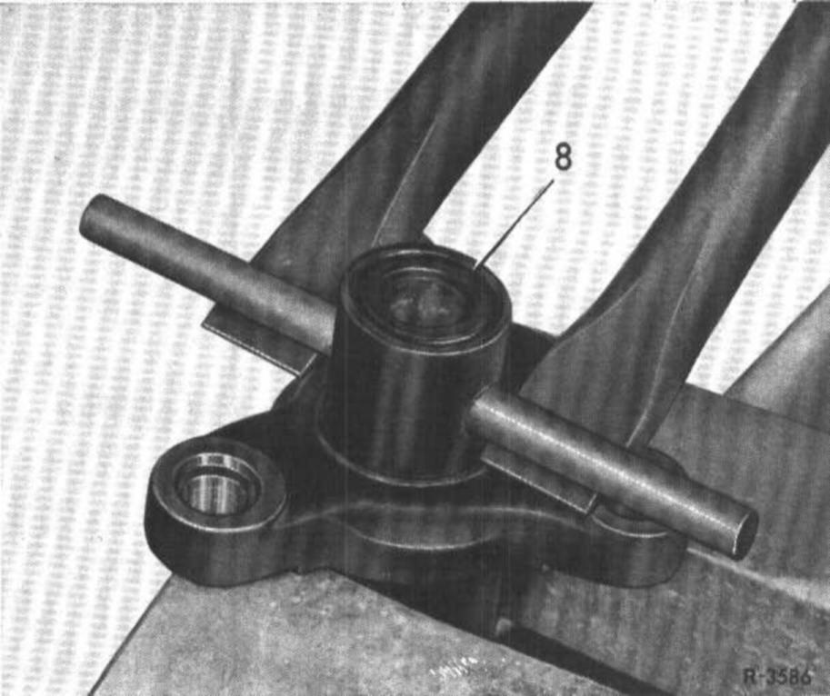
7 Insert mandrel into hole and pull centering sleeve out of propeller shaft by means of two mounting levers.
Installation
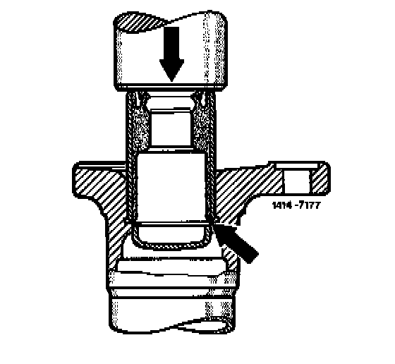
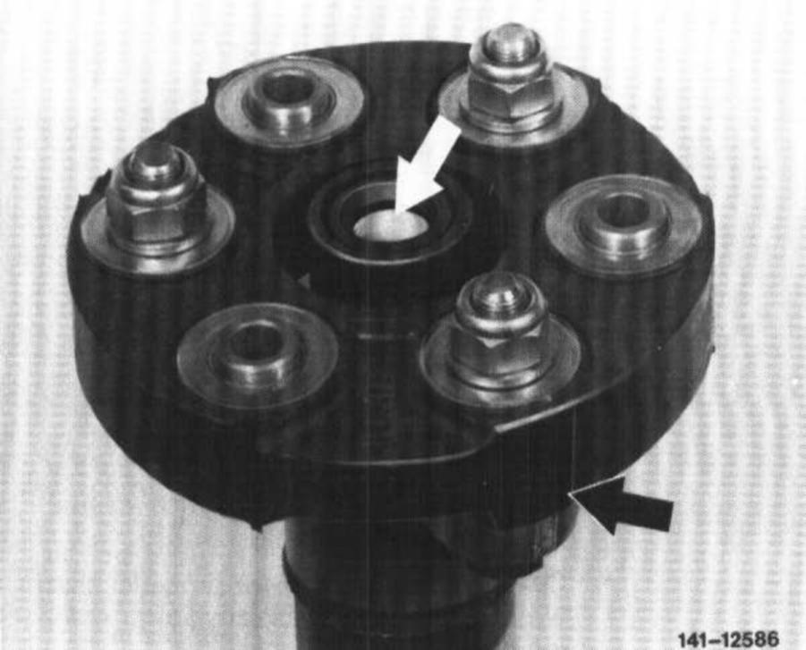
9 Install new centering sleeve up to stop by means of suitable mandrel (arrows).
note: Model 107.114,115, 116, 123, and 126.03
-Centering sleeve for front propeller shaft with standard companion plate and for rear propeller shaft
10 Fill cavity of centering sleeve with specified grease (approx. 6 grams per sleeve).
11 Propeller shafts with vibration eliminator.
Mount vibration eliminator and companion plate with hex socket screws.
Tightening torque of self-locking hex. nuts 45 Nm.
Identification Applied:
Attention! Pay attention to identification (arrow) applied prior to disassembly or already in place. Renew self-locking hex. nuts on principle.
Identification In Place:
The installation position is correct if the vulcanized arrow of eliminator points to hump of three-arm flange (identification already in place).
12 Propeller shaft without vibration eliminator:
Mount companion plate as shown on drawing. Tightening torque of self-locking hex. nuts with M 10 threads 45 Nm and M 12 threads 65 Nm.
Attention! Replace self-locking hex. nuts on principle.
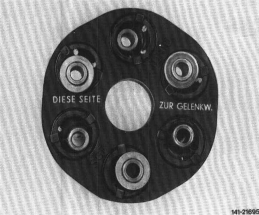
13 Mount tangentially soft companion plates (on vehicles with 5-speed transmission) in accordance with lettering "DIESE SEITE ZUR GELENKWELLE" ("This side toward propeller shaft")