Installation of Intermediate Bearing
Installation of propeller shaft intermediate bearing13 Insert rear protective cap (on models 107, 116, 123 and 126 only).
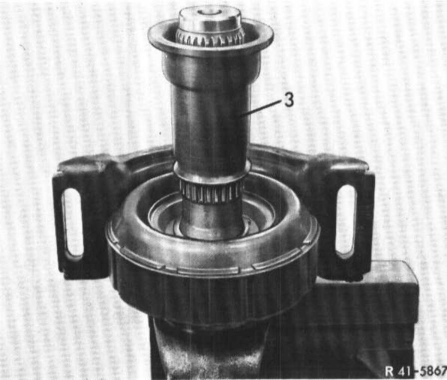
14 Press rubber mount with pressing-on sleeve (3) on yoke while paying attention to correct location of V-fold as follows:
On models 107 and 116 of 1st version the V-fold of rubber mount should point in driving direction.
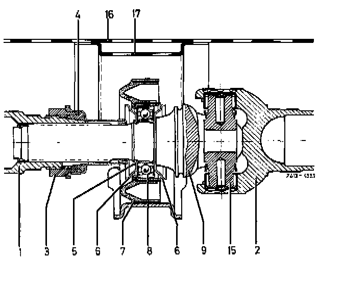
Models 107,116
1 Front propeller shaft
2 Rear propeller shaft
3 Clamping nut
4 Rubber sleeve
5 Locking ring
6 Protective cap
7 Propeller shaft intermediate bearing
8 Radial ball bearing
9 Yoke
15 Spider with needle bearing and bushings
16 Frame floor
17 Propeller shaft tunnel
On models 114 and 115 with two-piece propeller shaft the V-fold should point toward the rear opposite to driving direction.
On three-piece propeller shaft the V-fold of front rubber mount should point in driving direction and that of the rear rubber mount opposite to the driving direction.
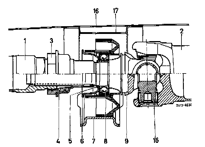
Models 114,115
1 Front propeller shaft
2 Rear propeller shaft
3 Clamping nut
4 Rubber sleeve
5 Locking ring
6 Protective cap
7 Propeller shaft intermediate bearing
6 Radial ball bearing
9 Yoke
15 Spider with needle bearing and bushings
16 Frame floor
17 Propeller shaft tunnel
Models 107,116 of 2nd version, 123 and 126 have a rubber mount with inner V-fold. Install rubber mount in such a manner that inner V-fold points toward universal joint.
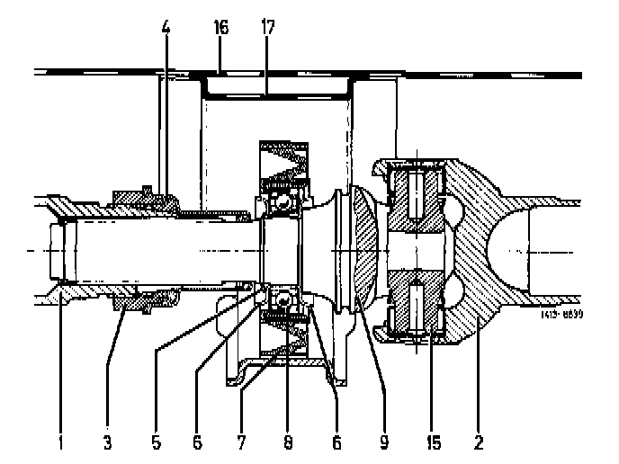
Models 107.116 (2nd version), 123 and 126
1 Front propeller shaft
2 Rear propeller shaft
3 Clamping nut
4 Rubber sleeve
5 Locking ring
6 Protective cap
7 Propeller shaft intermediate bearing
8 Radial ball bearing
9 Yoke
15 Spider with needle bearing and bushing
16 Frame floor
17 Propeller shaft tunnel
15 Plug front protective cap on vehicles up to July 1982.
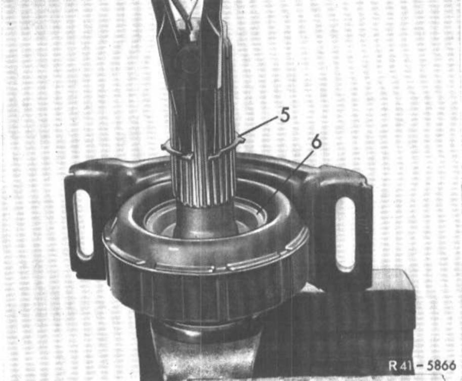
16 Insert locking ring (5) into groove of yoke in such a manner that cap rests tightly against inner bearing race.
Attention! The inside crown of locking ring is pointing toward the cap.
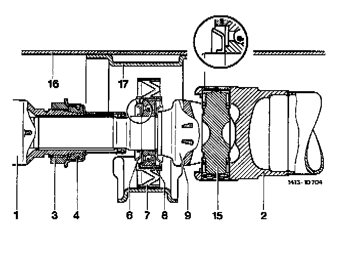
17 On vehicles starting August 1982, mount self-locking protective cap with pressing-on sleeve while making sure that the protective cap is resting well against radial ball bearing (cutout in image).
Attention! Use pressed-on protective cap only once.
18 Pull rubber sleeve (3) over splining of yoke. Make sure that the sleeve is correctly seated at small diameter.
19 Coat splining with specified grease.
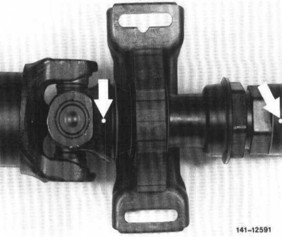
20 On vehicles up to July 1982, plug front and rear propeller shaft together as shown on drawing.
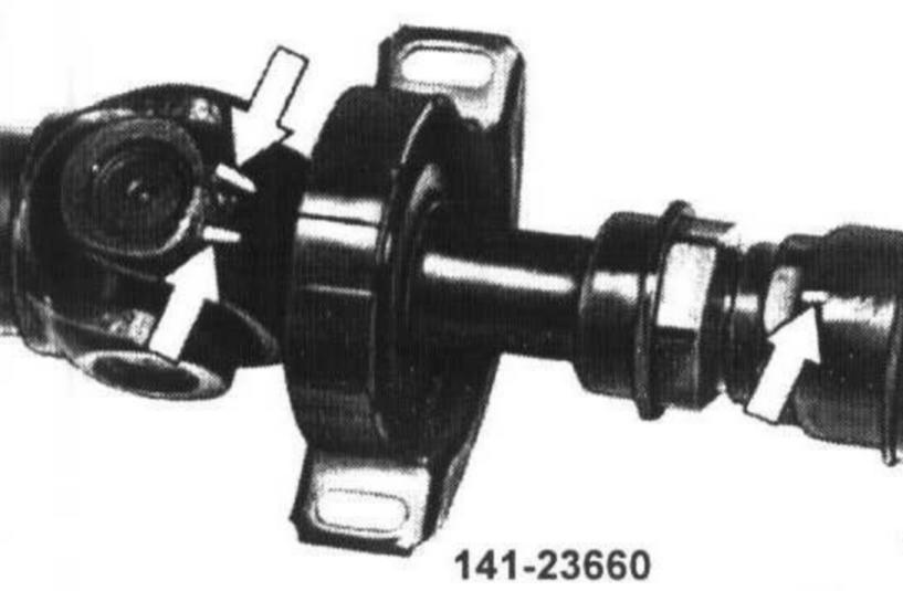
21 On vehicles starting August 1982 the identification is located on front and rear propeller shaft. The front shaft has one hump and the yoke of the rear shaft has two arrow-like humps (arrows). The hump of the front shaft should be located between the two arrows on yoke (arrows).