Valve Body: Service and Repair
Removal And Installation, Disassembly And Assembly Of Shift Valve Housing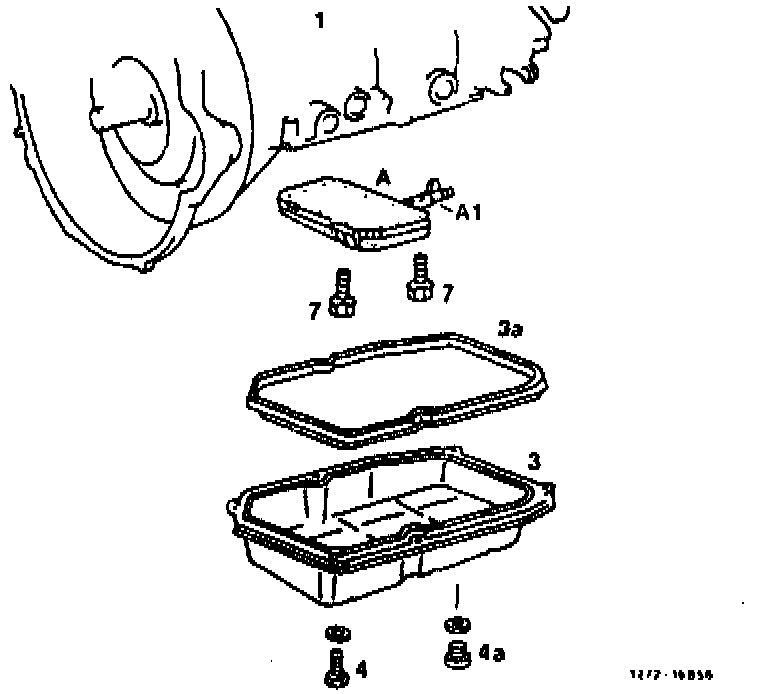
Drain plug (4a)
drain oil, following repairs, fill in and correct 14 Nm.
Fastening bolts (4)
screw off and in, 8 Nm, remove oil pan (3), check gasket (3a).
Shift valve housing (A)
remove and install; for this purpose, screw fastening bolts (7) off and in, 8 Nm; pay attention to different lengths of bolts. Range selector valve (A1) should enter driver.
Shift valve housing and accumulator housing
disassemble and assemble.
Removal And Installation
1 Unscrew drain plug and let oil run off.
2 Unscrew fastening bolts and remove oil pan.
3 Set shift lever to position "P".
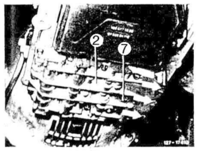
4 Unscrew fastening bolts (7) and remove shift valve housing (2).
Installation Note
The three bolts identified with arrows are 50 mm long, the remaining bolts 55 mm.
Tightening torque 8 Nm.
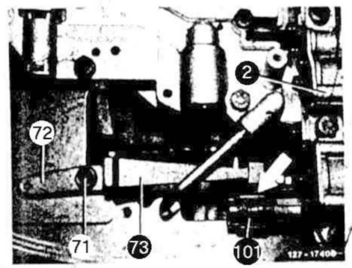
Make sure that the range selector valve (101) enters driver (arrow).
Disassembly And Assembly
General Notes
Observe particular cleanliness for all jobs on shift valve housing. The work should be done as much as possible on a plastic surface. Do not use fuzzy cloth; leather would be best. Upon disassembly, wash all parts and blow out with compressed air.
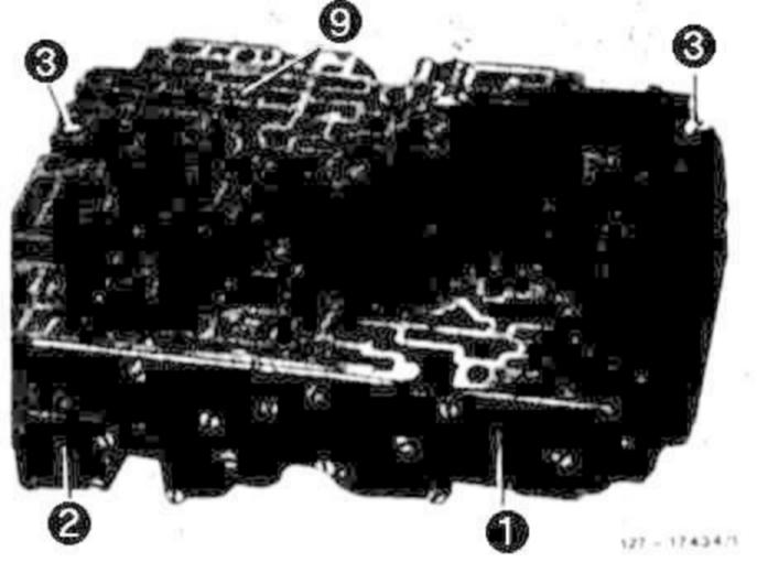
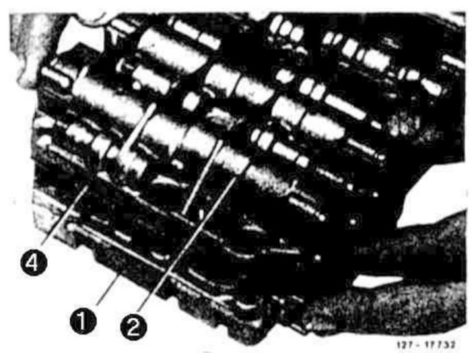
5 Unscrew both screws (3).
6 Hold shift valve housing (1) and accumulator housing (2) against each other and turn around.
Installation Note
Tighten screws (3) only to the extent that both housing parts can still be displaced in relation to each other, as fast as the screws permit. Insert plastic valve (9) into shift valve housing (1).
7 Lift off accumulator housing (2) with intermediate plate (4).
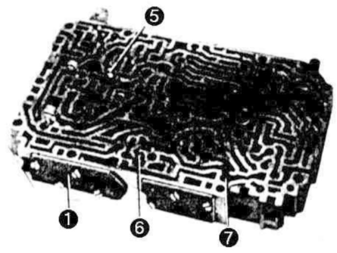
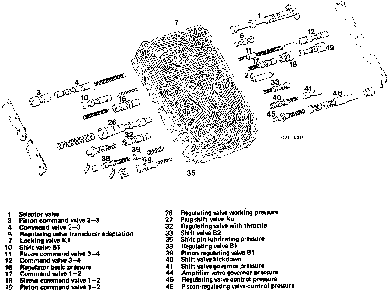
8 Remove all plastic valves and shift pin (7)
9 Remove all valve balls.
Caution!
Plastic valves (5 and 9, refer to Fig. item 5) are similar in shape and dimension; they differ only by a bore in valve item 9. If the valves are removed, they must be put back into their original position.
Installation Note
1st Version:
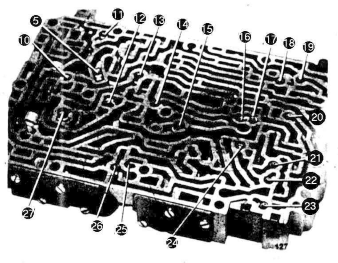
Depending on version the shift valve housing holds 17, 18 or 19 balls. During disassembly, make sure that the balls are not rolling away. During assembly. insert balls at correct point.
In addition, owing to the large number of shift valve housing versions, pay attention to number and color of the different valves.
2nd Version:
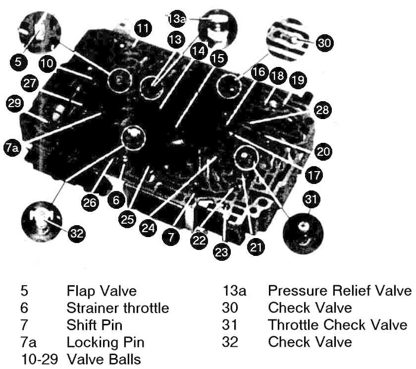
NOTE: Valve ball (28) is not installed on transmissions 722.315 and 722.303. A conical spring is located under valve ball (16). On some shift valve housing versions a pressure relief valve (13a) is installed instead of valve ball (13).
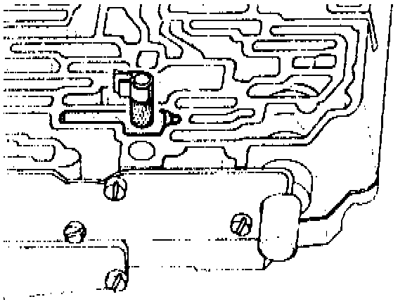
10 Insert chip strainer into feed channel to B2 shift valve. Installed as of transmission end no 729 001. Can also be installed in transmissions with lower transmission end no., part no. 126 270 02 98.
11 Unscrew lateral cover from shift valve housing and check pistons and valves for easy operation and chips.
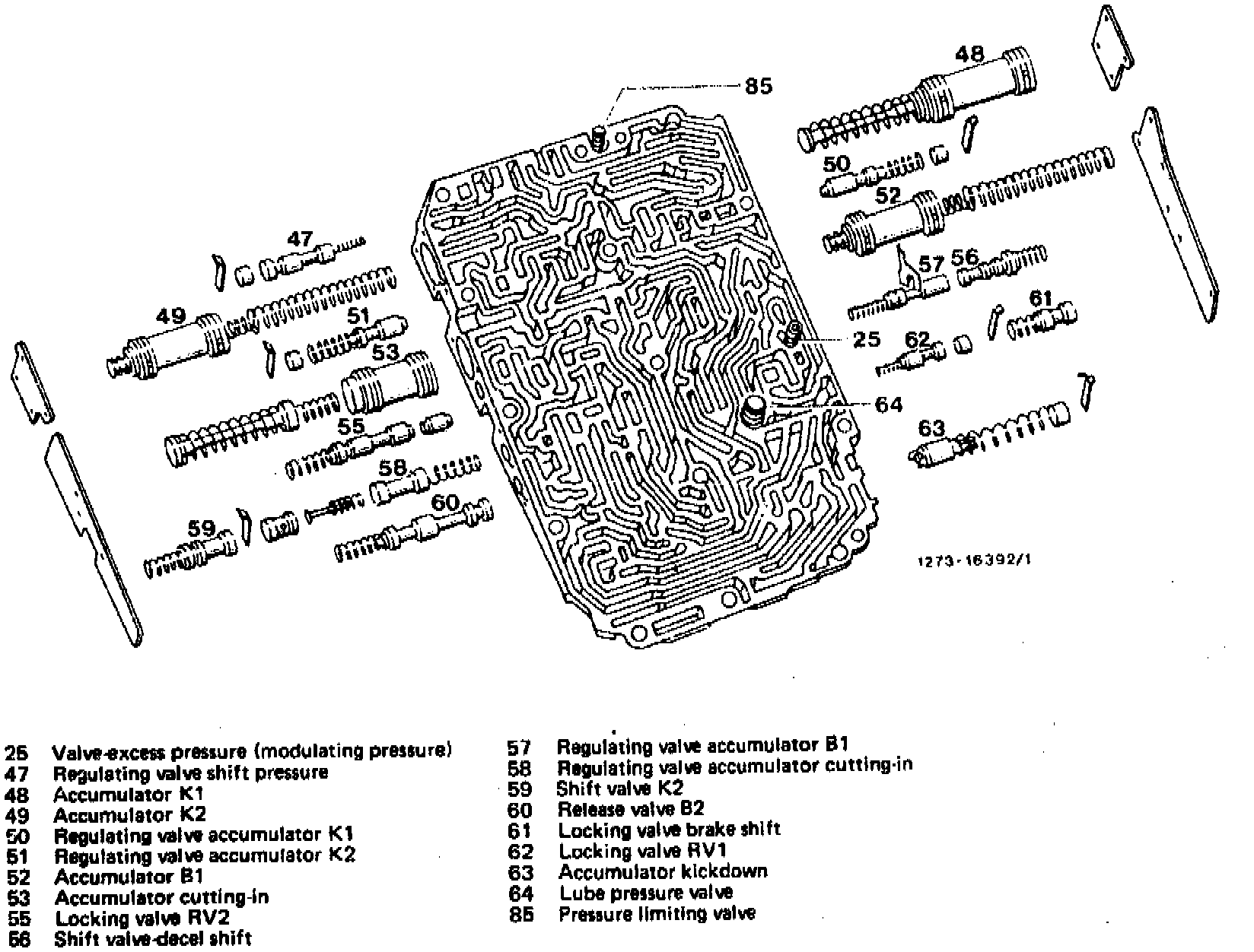
12 Unscrew lateral cover from accumulator housing and check pistons and valves for easy operation and chips.
Installation Note
The springs are installed in front of or behind valve depending on transmission type or vehicle model.
For this reason, when disassembling shift valve housing or accumulator housing, make sure of the sequence in which the valves and springs are installed.
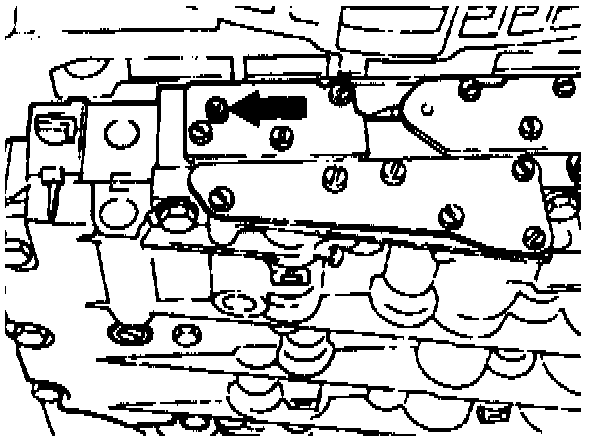
The arrow shows the location of the hex. socket screw for full throttle control pressure. Clockwise direction of rotation causes earlier full load or kick-down upshifts. Counterclockwise direction of rotation causes upshifts to occur later.