Removal and Installation of Primary Pump
Removal and Installation of Primary Pump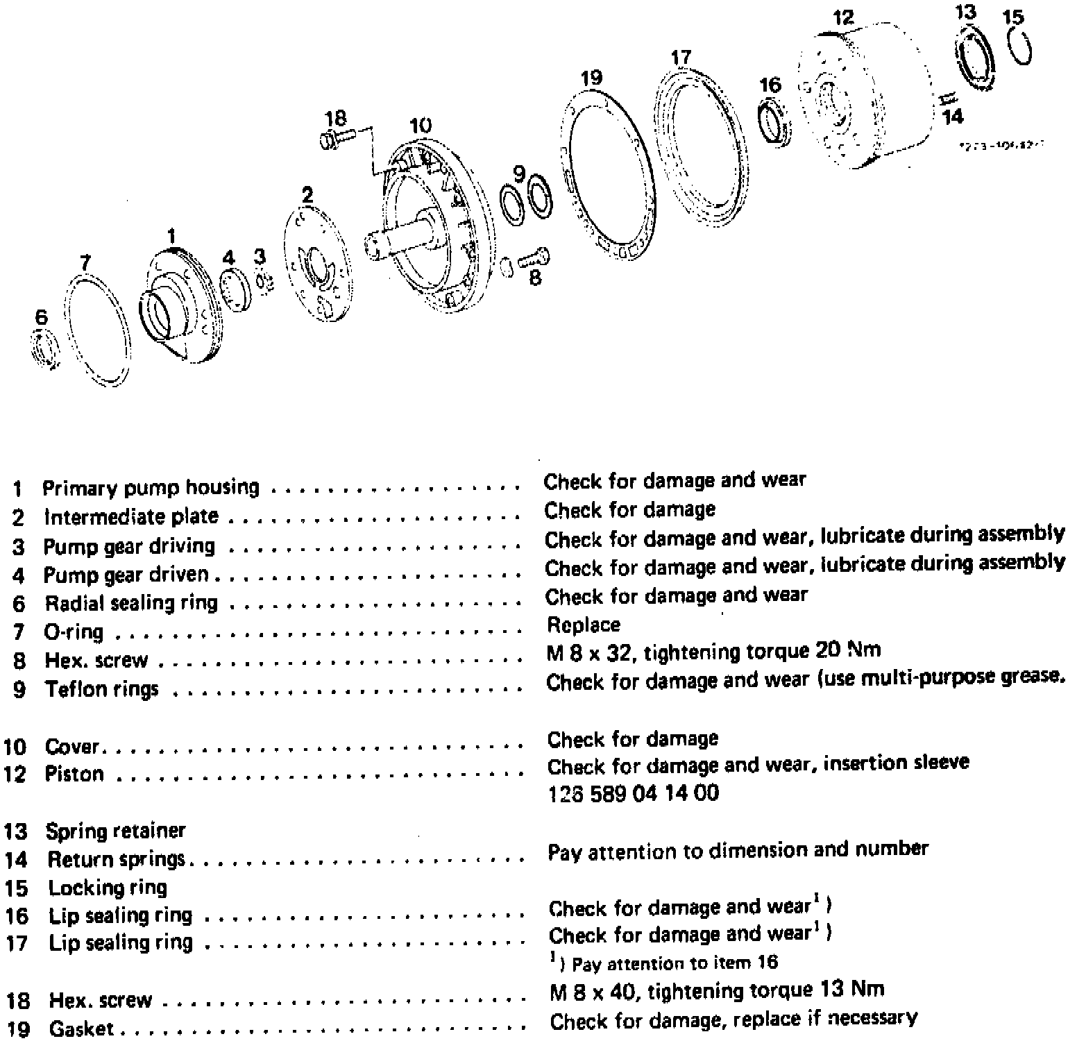
Return Springs For B 3 Piston
Transmission - 722.3
Number - 20
Wire dia. in mm - 0.6
Length, slack mm approx. - 24
Special Tool:
Removal
1 Unscrew fastening screws.
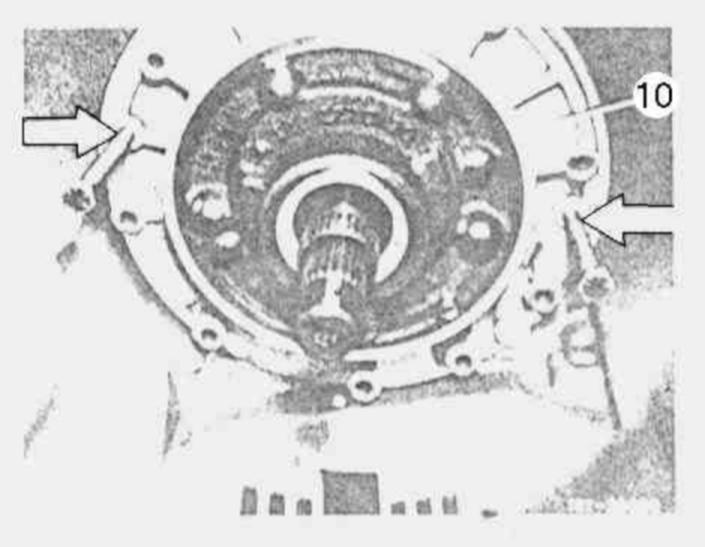
2 Screw two screws into tapped holes (arrows) and pullout front cover(10).
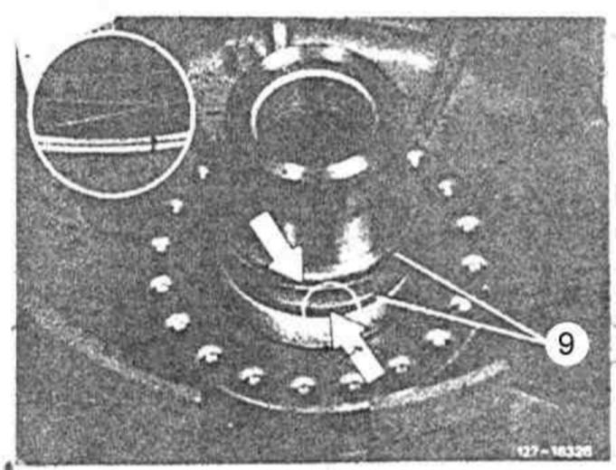
3 Remove the two teflon rings (9).
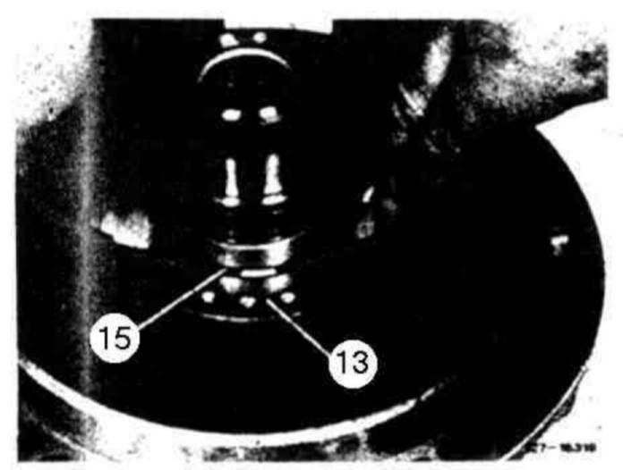
4 Push spring retainer (13) down and remove locking ring (15).
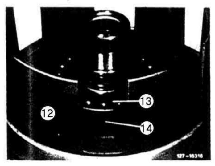
5 Remove spring retainer (13) and back pressure springs (14) for piston B 3.
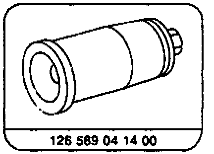
6 Pull out piston (12).
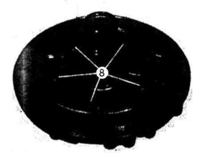
7 Loosen fastening bolts (8) and unscrew.
8 Take primary pump from front cover.
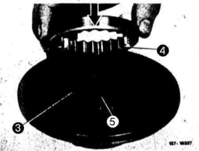
9 Take both pump gears (3 and 4) from pump housing.
Installation
Attention!
Check bearing bushing (5). If bearing bushing shows score marks or damage, renew primary pump.
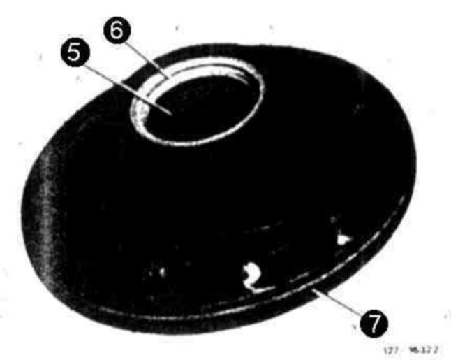
10 Check radial sealing ring (6) and renew, if required.
11 Renew 0-ring (7). Insert 0-ring into groove in such a manner that it is not twisted.
12 Lubricate both pump gears (3 and 4) and place into pump housing. Insert pump gear (4) in such a manner that chamfer (arrow) faces bearing bushing (5).
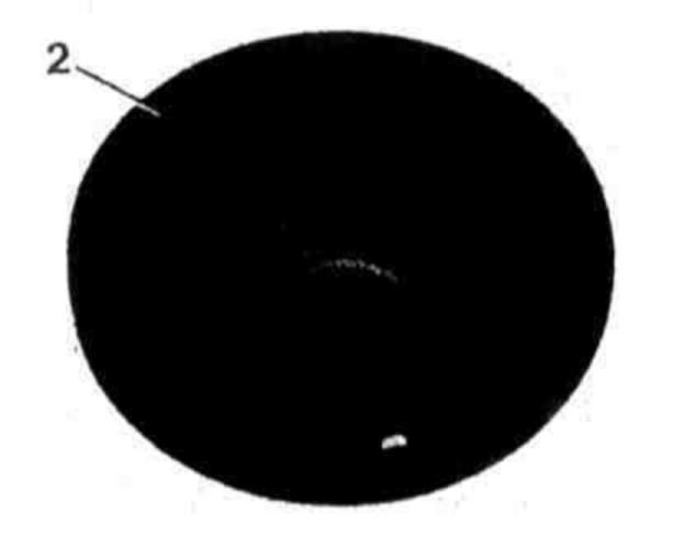
13 Place intermediate plate (2) on primary pump.
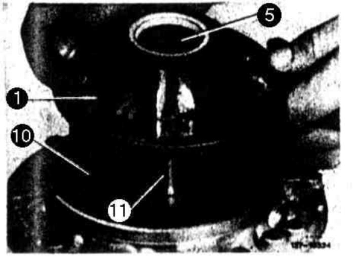
14 Place primary pump (1) into front cover (10), making sure that bearing bushing (5) is not damaged by stator shaft (11).
15 Insert fastening screws (8) and tighten to 20 Nm.
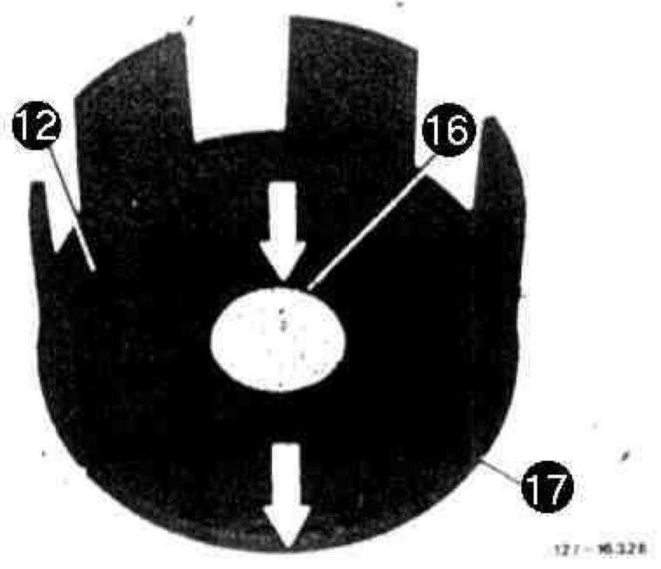
16 Check lip sealing rings (16 and 17) and renew, if required. Lip sealing rings should be installed in such a manner that the sealing lip is facing downwards (direction of arrow).
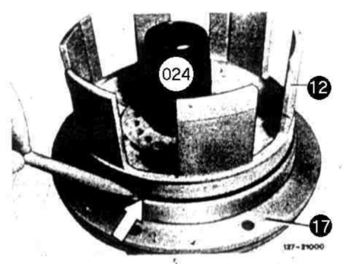
17 Place insertion sleeve (024) on front cover (10). Lubricate slide surfaces for lip sealing rings.
18 Lubricate lip sealing rings on piston. Insert piston (12) in such a manner that pin (on piston) and bore (in front cover) are in alignment.
19 Carefully push down piston without canting, push down with a pin at outer lip sealing ring (arrow), if required.
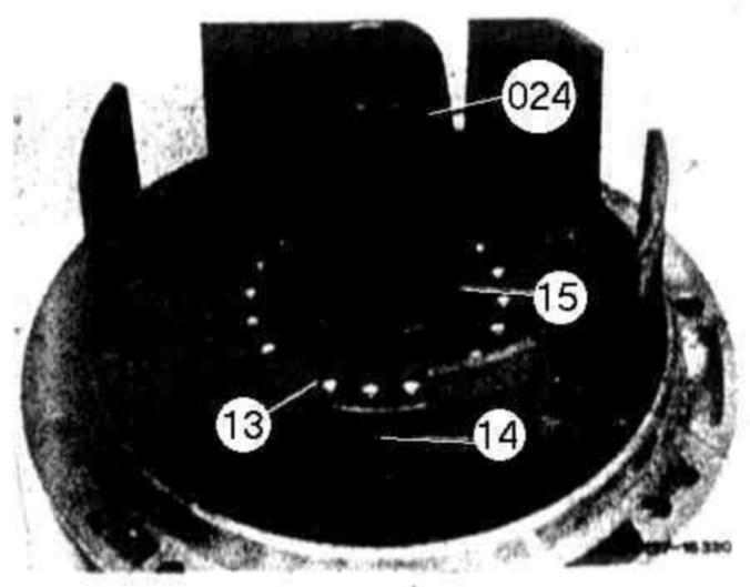
20 Mount back pressure springs (14) and spring retainer (13).
21 Slip locking ring (15) over installation sleeve (024). Hold locking ring at bottom and pull off installation sleeve.
22 Push spring retainer (13) down with locking ring (15), until locking ring engages in its groove.
Note: It the multiple plate brake B3 (Japan,USA 1988) is provided with a spring retainer (item 80), the assembly device 201 589 12 43 00 is required to push down spring retainer.
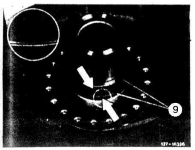
23 Insert teflon rings (9) with grease. Make sure that the ring interfaces (arrow) remain in touch. If required, remove rings again and shape to a smaller diameter.
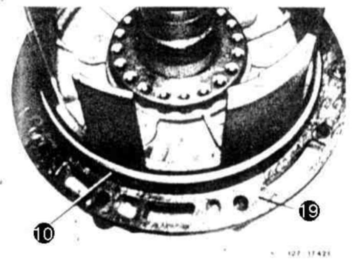
24 Place gasket (19) fitting with hole pattern on front cover (10).
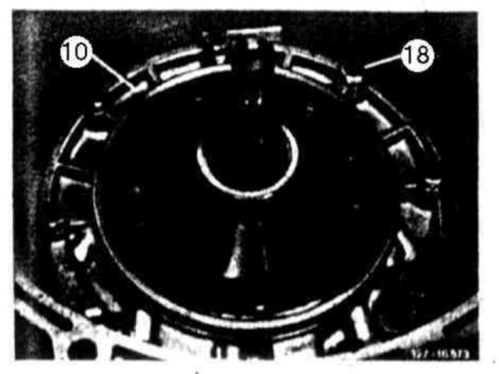
25 Mount front cover (10). Tighten fastening screws (18) to 13 Nm.
Note Make screws free of grease and coat with nonhardening sealing compound. Up to transmission end No. 313 790, close assembly thread bores with 2 short screws.