Checking Alignment of Rear Shock Absorbers
Checking alignment of rear shock absorbers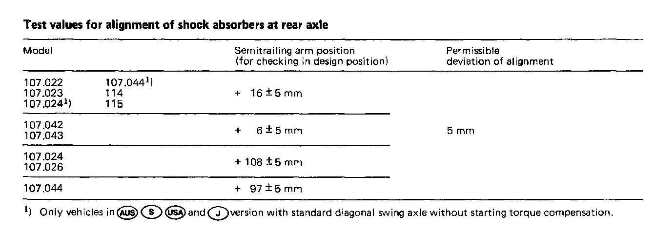
Note: Excessive deviations in alignment of shock absorber suspension points may lead to increased wear in shock absorber and subsequent rumbling noises and leaks of piston rod seal. In extreme cases, the driving comfort may be impaired (hardening of suspension by increased friction).
A checkup and, if required, a correction of the shock absorber alignment should therefore be performed following pertinent adjustment and reconditioning jobs of respective frame members at rear end. The shock absorbers will be checked for alignment with the axle installed in design position of vehicle.
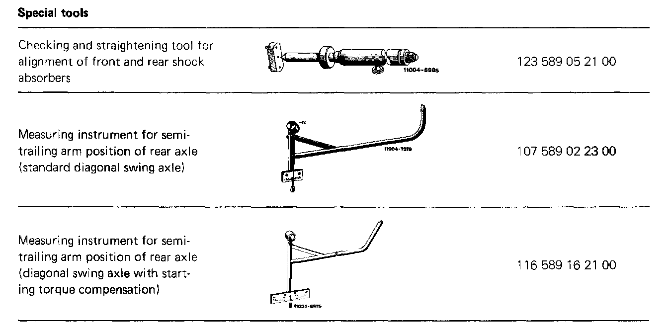
The testing and adjusting Tool 107 589 00 21 00 valid up to now for checking alignment of shock absorbers on rear axle, has been replaced by the testing and adjusting tool 123 589 05 21 00, used for front and rear axle of models 116 and 123.
Attention! When removing gas pressure shock absorbers with separating piston or with piston rod mounted at top, with vehicle jacked up and axle half relieved, make sure that the piston rod is not turning along when loosening upper suspension. Since in this condition the resilience stop in shock absorber rests against operating piston, the attachment of operating piston to piston rod may then suddenly extend piston rod and the oil in shock absorber would flow out (risk of an accident).
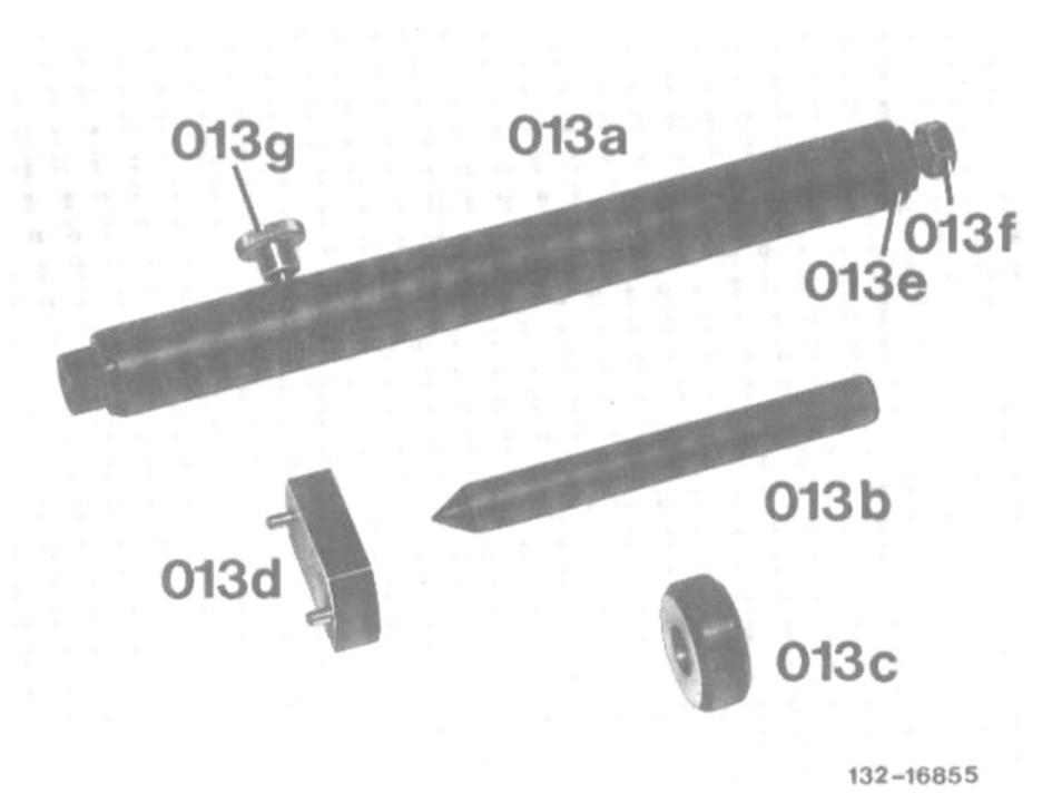
013 Testing and adjusting tool
013a Adjusting bolt
013b Testing and adjusting pin
013c Test sleeve
013d Test plate
013e Washer
013f Hex nut
013g Tightening screw
Test procedure
1. Remove rear shock absorbers or spring struts.
2. Load vehicle rear end in this condition until specified semitrailing arm position is attained.
3. Attach testing and adjusting tool to shock absorber dome of frame floor.
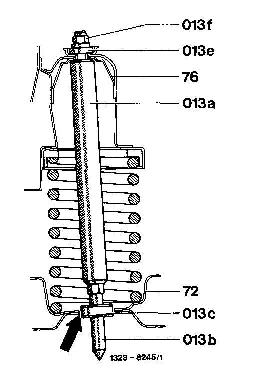
013 Testing and adjusting tool
013a Adjusting bait
013b Testing and adjusting pin
013c Test sleeve
013e Washer
013f Hex nut
72 Semitrailing arm
76 Mandrel on frame floor
4. Check alignment with the sleeve (013c). Uniform clearance all-around in relation to semitrailing arm (refer to arrow) indicates 0 mm deviation. For corrections, remove test sleeve and use testing and adjusting pin.