Stabilizer Link: Service and Repair
Removal and installation of wheel carrier support on torsion bar (Diagonal swing axle with starting torque compensation)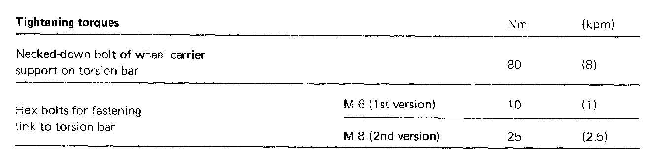
Removal
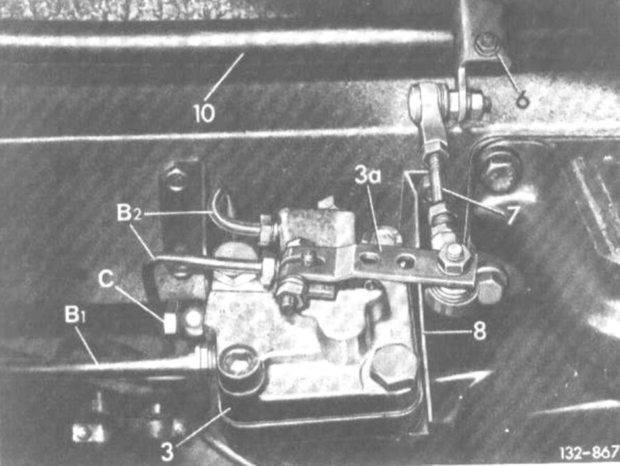
1. On vehicles with level control, disconnect connecting rod (7) for level control from lever (3a).
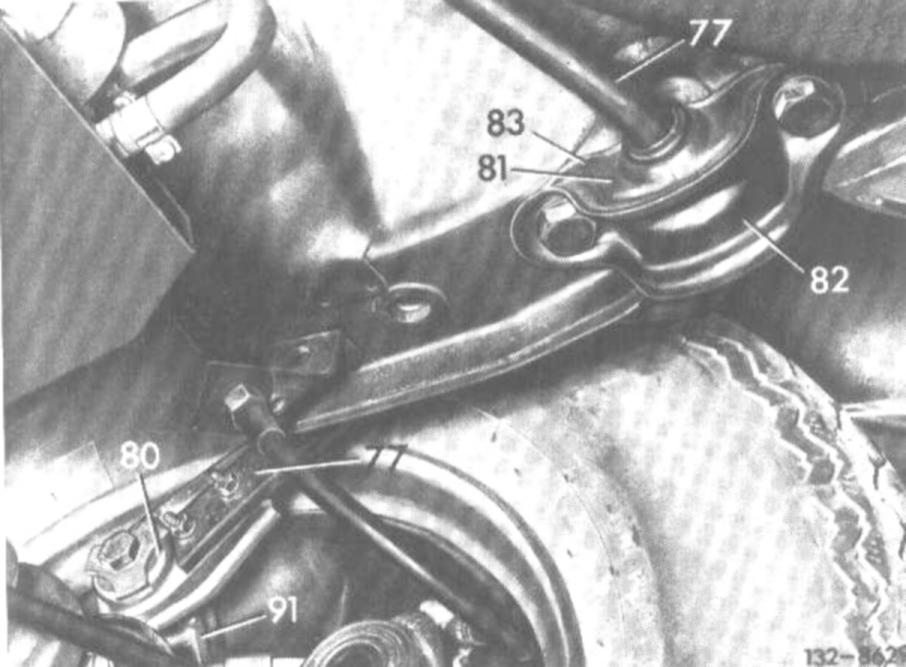
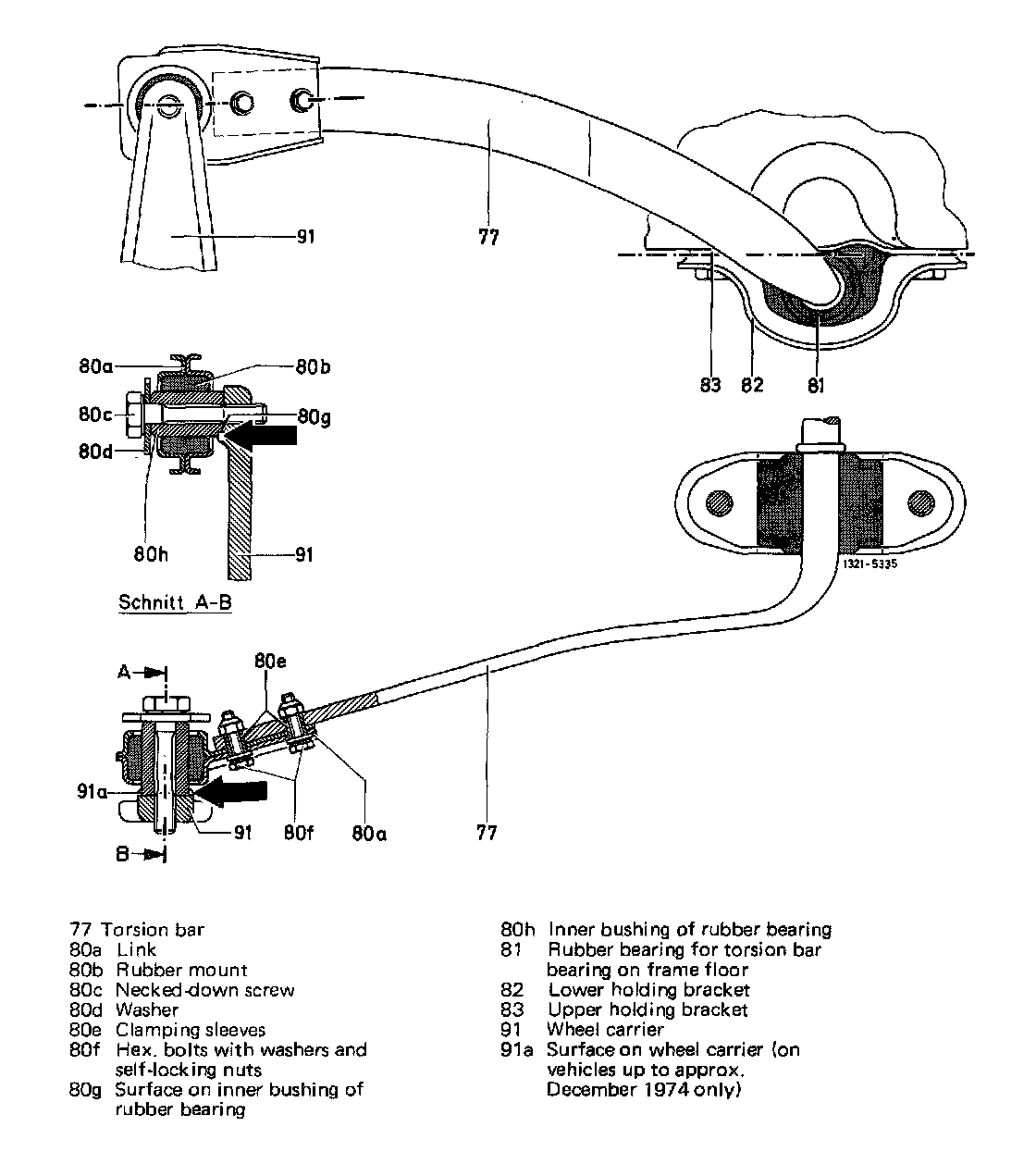
77 Torsion bar
80 Wheel carrier support on torsion bar
81 Rubber mount
82 Lower holding bracket
83 Upper holding bracket
91 Wheel carrier
2. Unscrew necked-down bolts of wheel carrier support at left and right.
3. Lift vehicle and remove both rear wheels.
4. Loosen both hex bolts of link at left and right on torsion bar and remove both links.
Installation
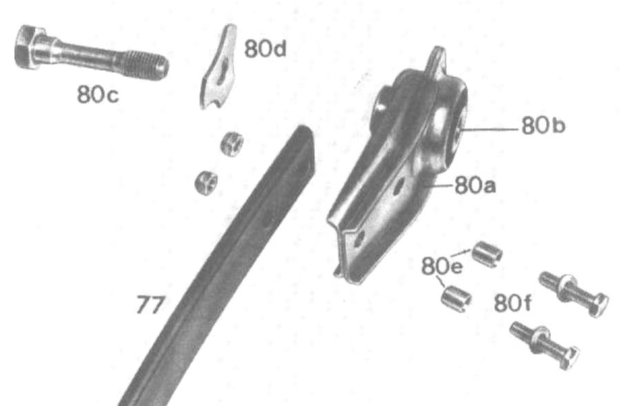
77 Torsion bar
80a Link
80b Rubber mount
80c Necked-down screw
80d Washer
80e Clamping sleeves
80f Hex bolts with washers and self-locking nuts
5. Introduce clamping sleeves into new link with conical side toward torsion bar.
Attention! Clamping sleeve should be flush with link
6. Mount link at left and right to torsion bar by means of hex bolts.
7. Check threads for necked-down screws in wheel carrier for easy operation and refinish, if required
8. Mount both rear wheels and lower vehicle end - it required by loading trunk - until the surface of the inner bushing of rubber mount (80g) in link of torsion bar is in alignment with surface of wheel carrier (91a)
Note: On vehicles without surface on wheel carrier (starting approx. January 1975) tighten necked-down screw of wheel carrier support on torsion bar only when the vehicle is on its wheels ready for driving.
9. Connect torsion bar support to wheel carrier.
Attention! The contact surfaces must be absolutely clean and free of grease. When tightening, pay attention to correct seat of inner bushing of rubber bearing on wheel carrier.
10. Additionally on vehicles with level control:
a) Attach connecting rod to lever of level controller.
b) Check vehicle level and correct, if required.