Gear Disassembly
POWER STEERING GEAR
Disassembly
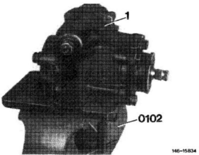
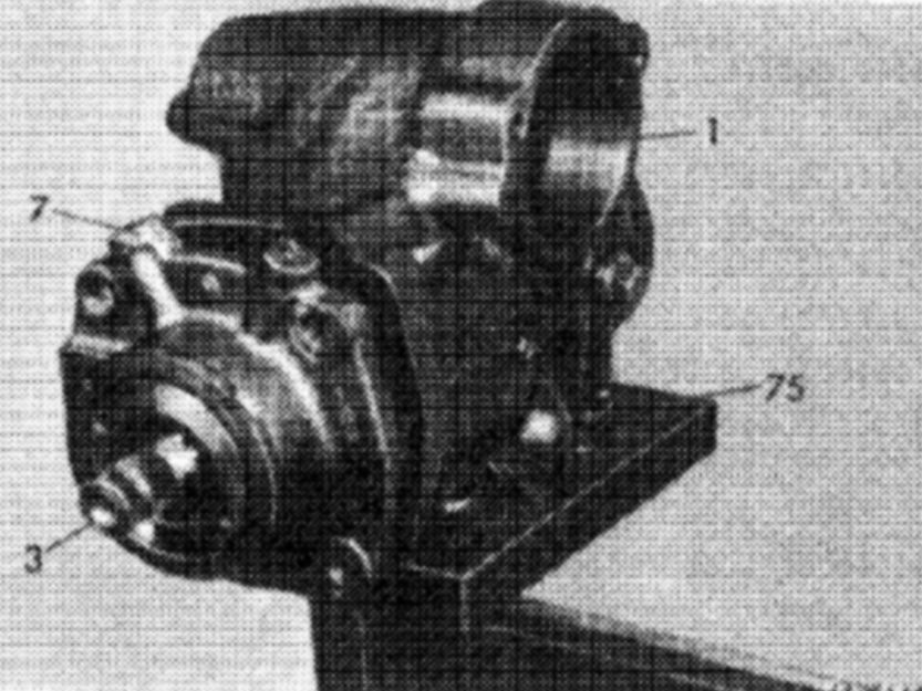
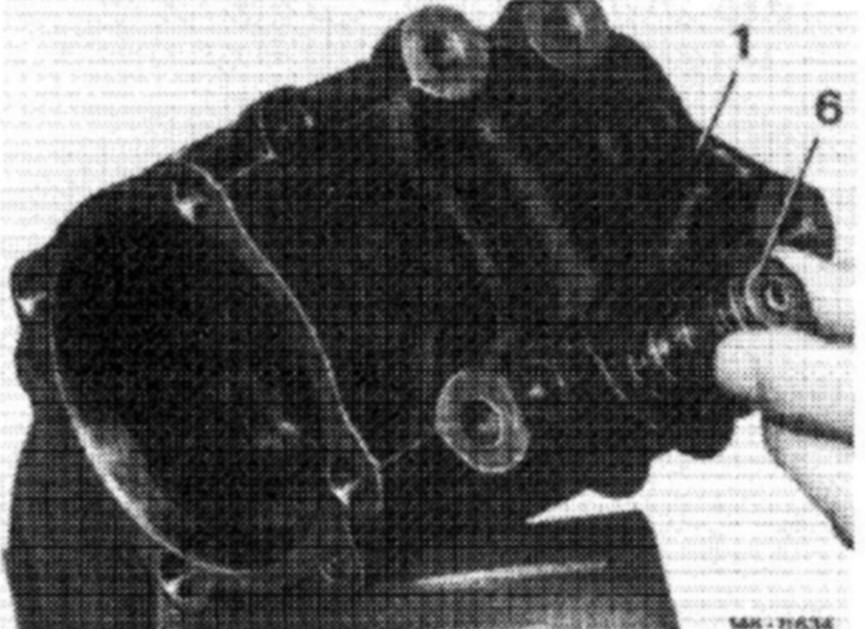
1. Fasten steering (1) to assembly device (0102).
Special tool 123 589 03 59 00
2. On steering 3rd version (with automatic compensation for play) turn steering worm until working piston is slightly in left hand or right hand lock.
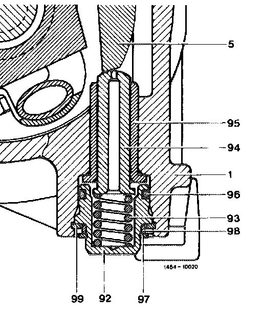
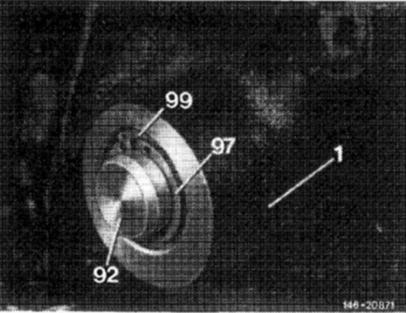
3. Remove locking ring (97) from cover (92), then remove thrust ring (98) from steering case.
Remove locking ring (99) from steering case (1).
Remove compression spring (93). spring bolt (94) and bushing (95).
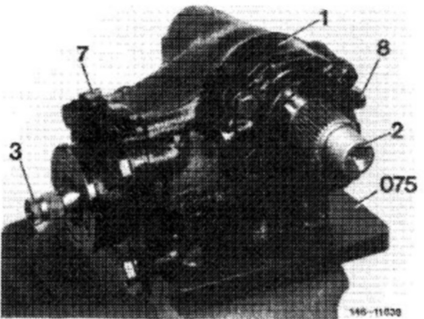
4. Unscrew hex. screws for fastening casing cover (8) to steering case (1).
5. Unscrew self-locking hex. nut (57) from adjusting screw (47), while applying counter hold to adjusting screw.
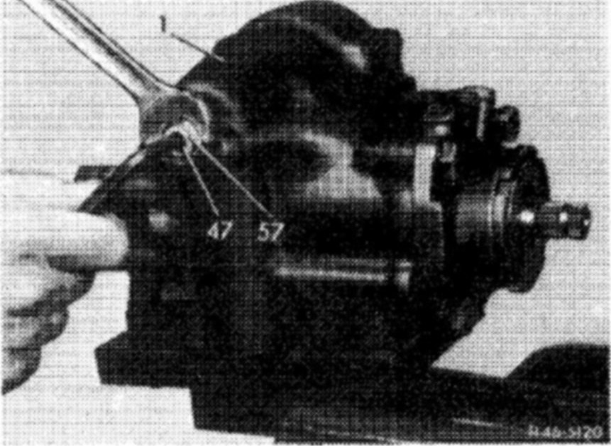
6. In center position of steering, turn adjusting screw to the right, which will force pitman shaft including casing cover out of steering case.
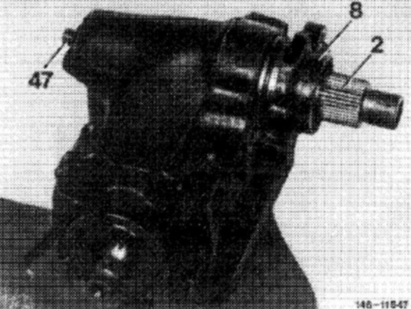
7. Remove casing cover (8) from pitman shaft (2).
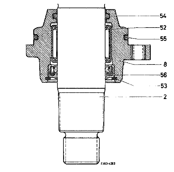
8. Remove O-rings (54 and 55) from casing cover.
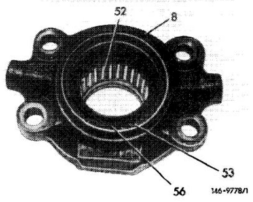
9. Remove locking ring (53) and radial sealing ring (56) from casing cover (8).
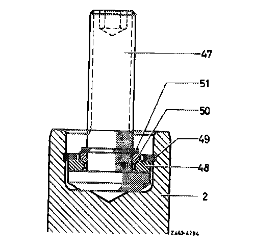
10. Take locking ring (51) out of adjusting screw (47), then remove thrust ring (50).
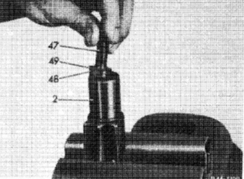
11. Remove locking ring (49) from pitman shaft (2). Remove adjusting screw (47) including thrust washer (48).
12. Unscrew hex. screws for fastening bearing cap (7) to steering case (1).
13. Slip steering coupling on steering worm, turn steering worm to the left until bearing cap is pushed slightly out of steering case.
Attention:
Do not turn too far, since otherwise the balls may fall out of ball circuit.
14. Remove bearing cap together with steering worm and working piston out of steering case.
15. Place measuring device on splining of steering worm and measure friction torque of ball circuit. The friction torque steering nut - steering worm should amount to 5-50 Ncm (i.e. 50 g in notch "10" as lowest or 500 g in notch "6" to "12" as highest friction torque).
Special tool 116 589 03 21 00
If the friction torque is lower, the ball circuit has play; if it is higher, ball circuit is damaged. In both cases, replace the steering case.
16. The friction torque can also be measured with torque wrench in combination with respective socket.
Special tool 123 589 02 21 O0 and 123 589 00 08 00
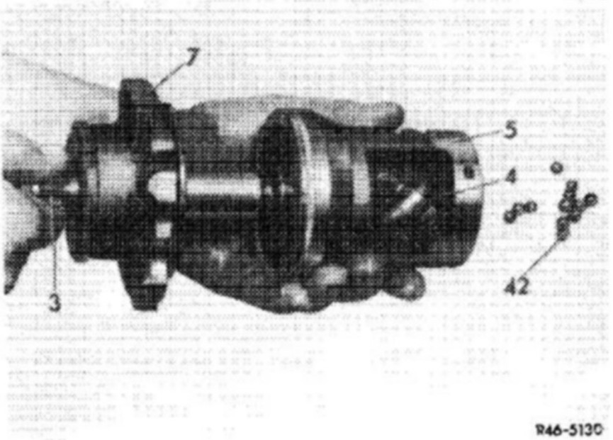
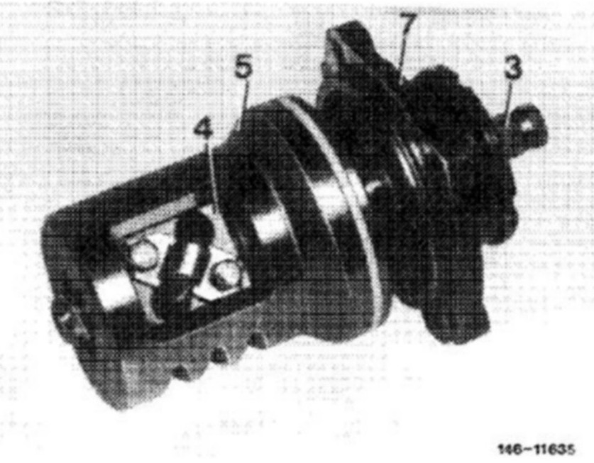
17. Screw steering worm (3) out of steering nut (4), making sure that no balls (42) are lost.
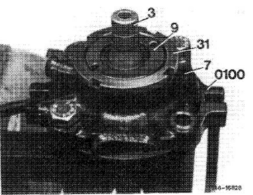
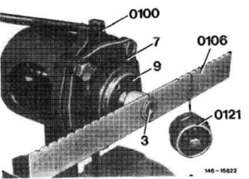
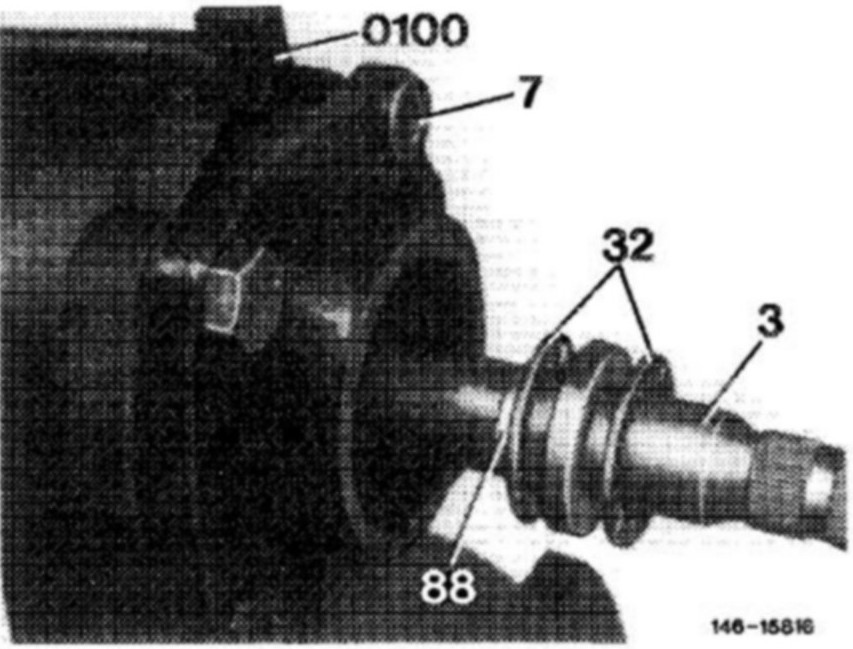
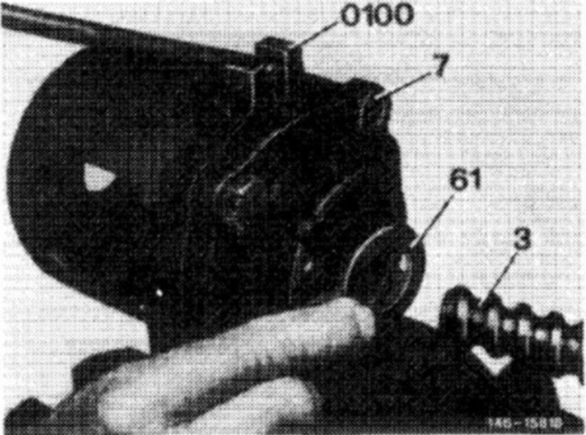
18. Remove O-ring from bearing cap (7) and fasten bearing cap in device (0100).
Special tool 123 589 02 59 00
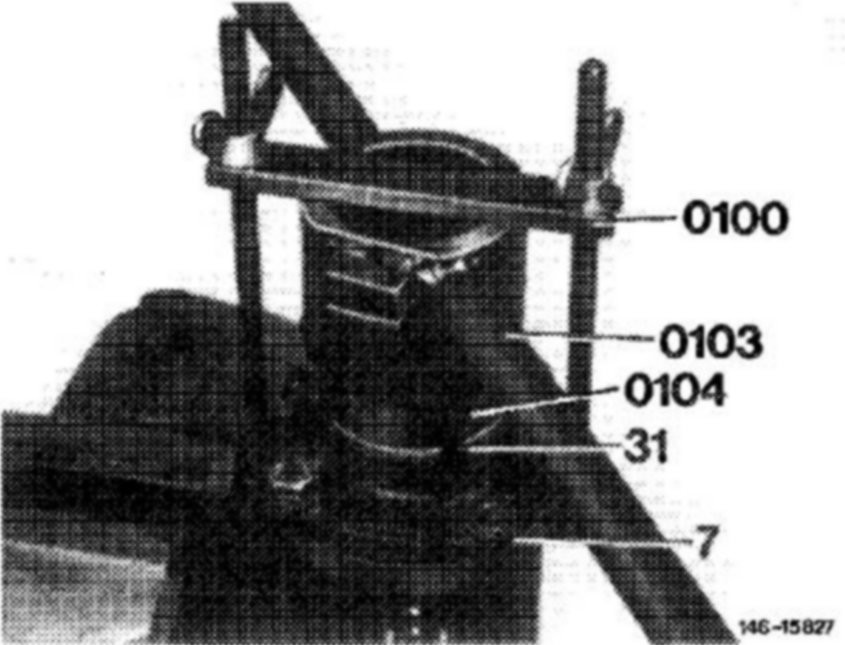
19. Unscrew slot nut or hex. nut with tommy handle (0103) and unscrew pertinent insert (0104) from bearing insert.
Special tool 126 589 00 16 00 and 123 589 01 07 00 or 123 589 09 09 00
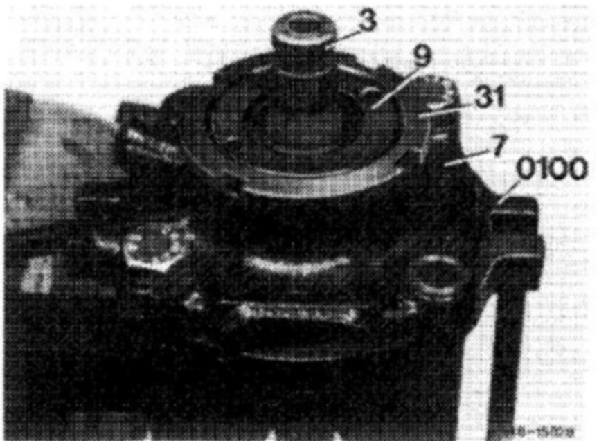
Layout bearing insert with slot nut
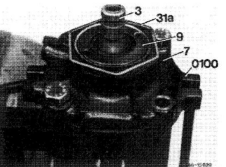
Leyout bearing insert with hex nut
20. Unscrew bearing insert (9) with pin wrench from bearing cap (7).
Special tool 000 589 00 05 00
Note: Bearing insert can also be unscrewed by means of the adjustable pin wrench.
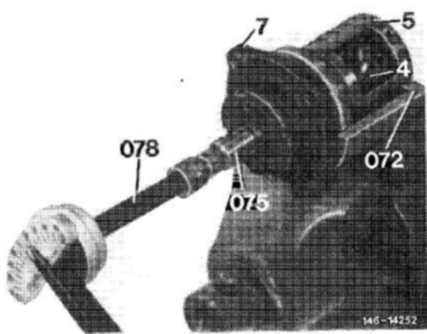
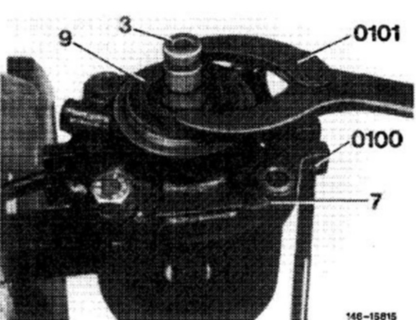
21. Remove steering worm (3) from bearing cap (7), remove axial cyl. roller cage (32) from steering worm.
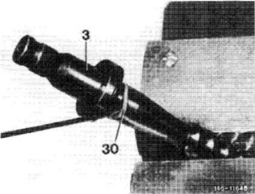
22. On 1st version, remove bearing cap/steering worm sealing ring (30) and O-ring (29) from steering worm (3).
Bearing cap and steering worm 1st version.
Bearing cap with neck, sealing ring (teflon) and O-ring on steering worm
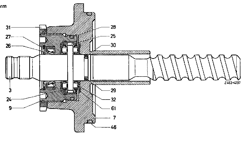
3 Steering worm
7 Bearing cap
9 Bearing insert
24 Axial washer
25 Needle sleeve
26 Radial sealing ring
27 Locking ring
28 O-ring
29 O-ring
30 Sealing ring (teflon)
31 Slot or hex. nut
32 Axial cyl. roller cage
46 O-ring
61 Axial washer
Bearing cap and steering worm 2nd version.
Bearing cap without neck, sealing ring (teflon) and O-ring in bearing cap
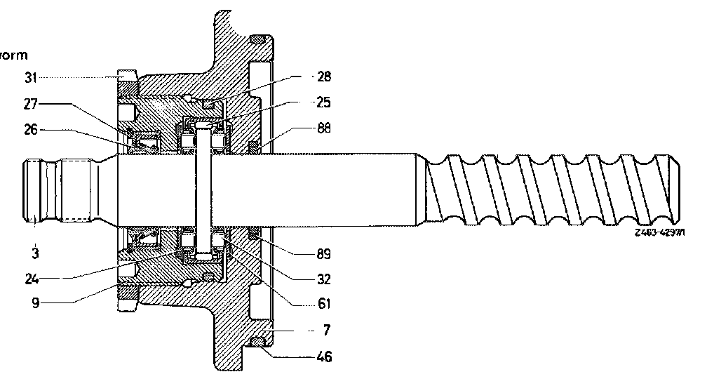
3 Steering worm
7 Bearing cap
9 Bearing insert
24 Axial washer
25 Needle sleeve
26 Radial sealing ring
27 Locking ring
28 O-ring
31 Slot or hex. nut
32 Axial cyl. roller cage
40 O-ring
61 Axial washer
88 Sealing ring (teflon)
89 O-ring
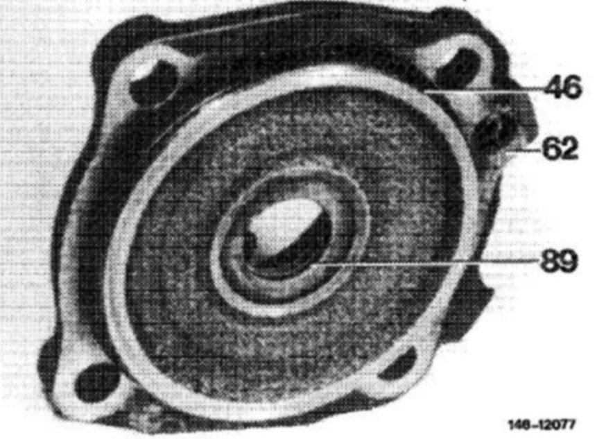
23. On 2nd version bearing cap/steering worm remove sealing ring (89) and O-ring from bearing cap.
24. Remove axial washer (61) from bearing cap (7).
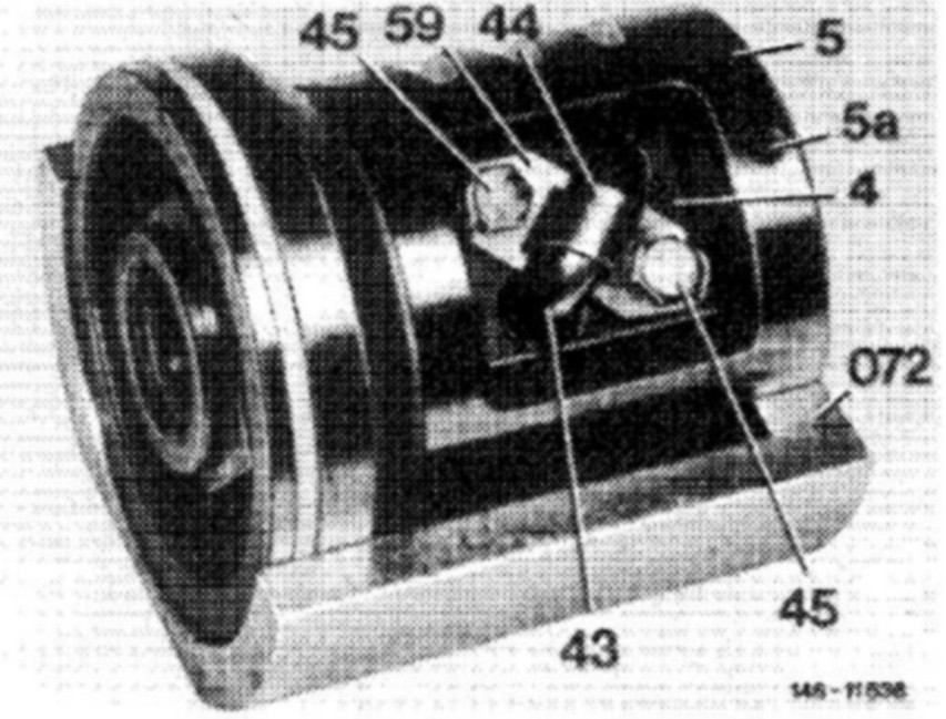
25. Unbend locking plate (59), unscrew hex. screws (45), remove locking plate, fastening clip (44) and both ball guide halves (43).
Special tool 201 689 02 69 00
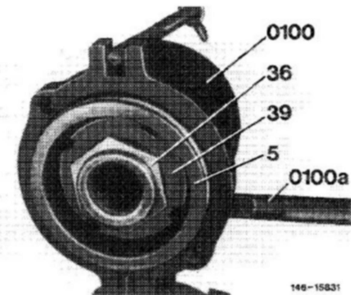
26. Clamp working piston (5) into device (0100) and secure with plug (0100 a).
Special tool 123 589 02 59 00
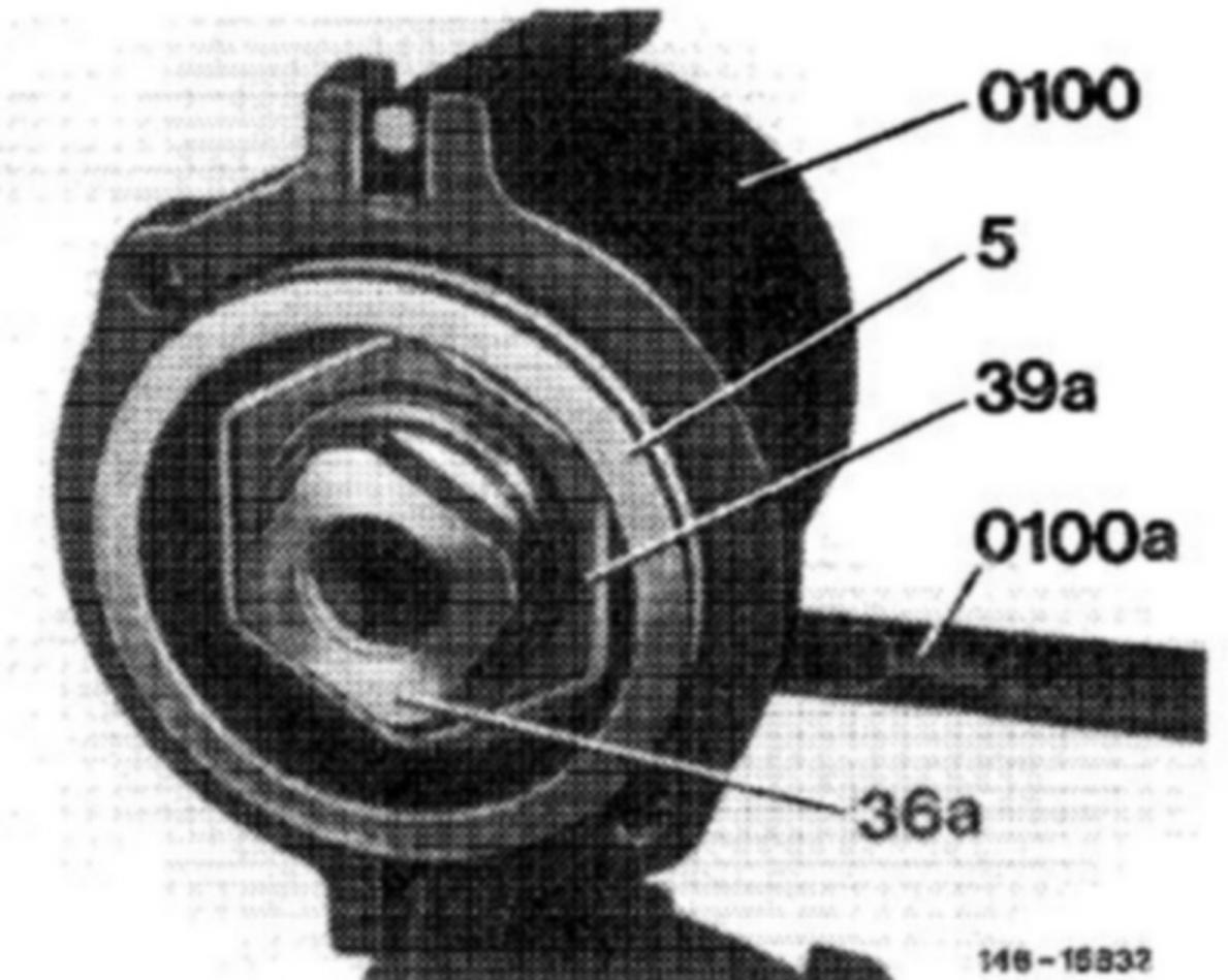
Layout screw cover (36) with hexagon SW 36 or 46 and slot nut (39)
Layout screw cover (36 a) with square head and hex nut (39 a)
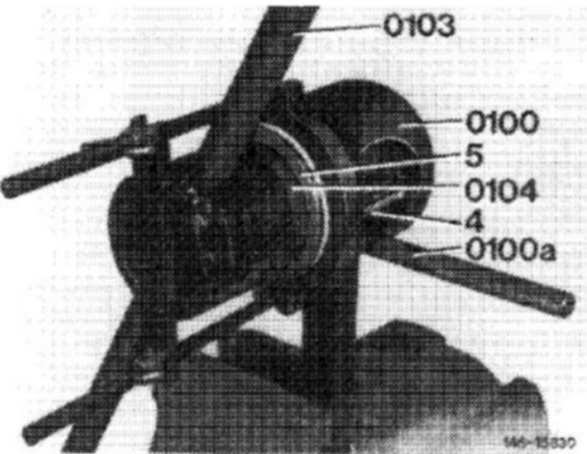
27. Unscrew slot nut or hex. nut with pertinent insert (0104) including tommy handle (0103), then unscrew screw cover with pertinent insert.
Special tool for slot or hex. nut 126 589 00 16 00, 123 589 00 07 00, 123 589 09 09 00
Special tool for screw cover 123 589 01 16 00, 123 589 05 09 00, 123 589 06 09 00, 123 589 07 09 00
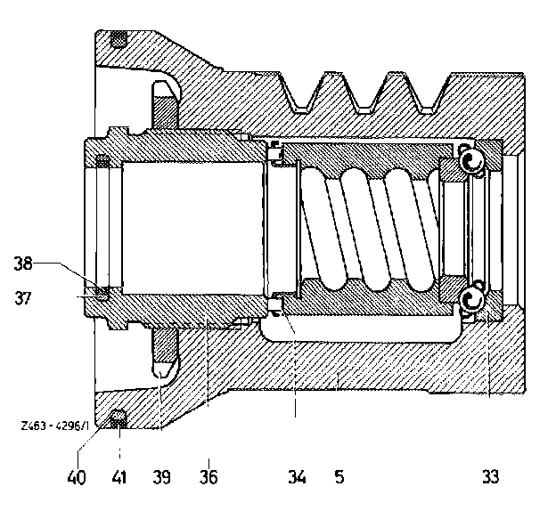
28. Take sealing ring (teflon) (38) and O-ring (37) from screw cover (36).
29. Remove axial cyl. roller cage (34) from steering nut (4) and steering nut from working piston (5).
30. Remove axial angular ball bearing (33) from working piston.
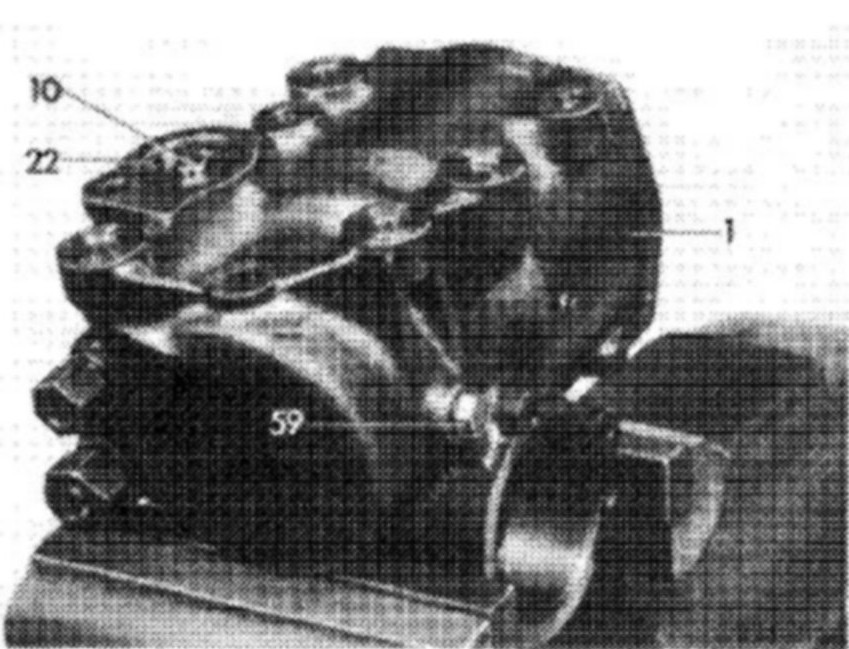
31. Remove locking ring (22) and closing cover (10) from steering case.
32. Remove control valve (6) from steering case (1), making sure that the springs on control valve 2nd, 3rd and 4th version are not falling out of reaction piston.
33. Remove O-ring (21) from closing cover.