Remove and Install Steering Shaft
REMOVE AND INSTALL STEERING SHAFTData
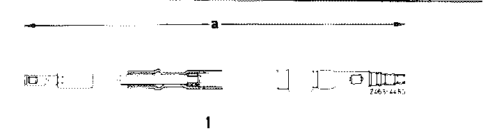
Length "a" of steering shaft (reference dimension)
with male treads 687 mm
with female threads 668.5 mm
Tightening Torques Nm (kpm)
Hex. nut or countersunk screw for attaching
steering wheel to steering shaft
M 14 x 1.5 50 (5)
M 16 x 1.5, M 18 x 1.5 80 (8)
Hex socket screw to steering coupling 25 (2.5)
Note:
Since the OD of the closing ring of the steering shaft is larger than the ID of the needle bearing in bearing body, the steering shaft must be removed together with bearing body.
Removal
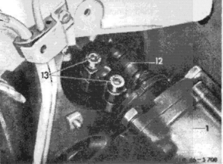
1. Unscrew upper hex. socket screw (13) from steering coupling (12) with a double joint wrench.
2. Remove steering wheel.
3. Remove rubber cover for combination switch (10) from jacket tube. Unscrew switch on bearing body (12) and pull out slightly.
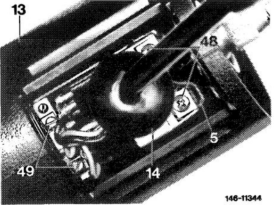
4. Unscrew both slotted screws (49) for cable of carbon contact on combination switch.
5. Unscrew hex. socket screws from jacket tube and pull steering shaft including bearing body out of jacket tube in upward direction.
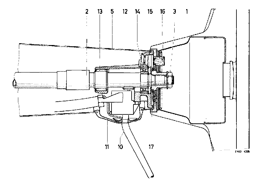
1 Steering wheel
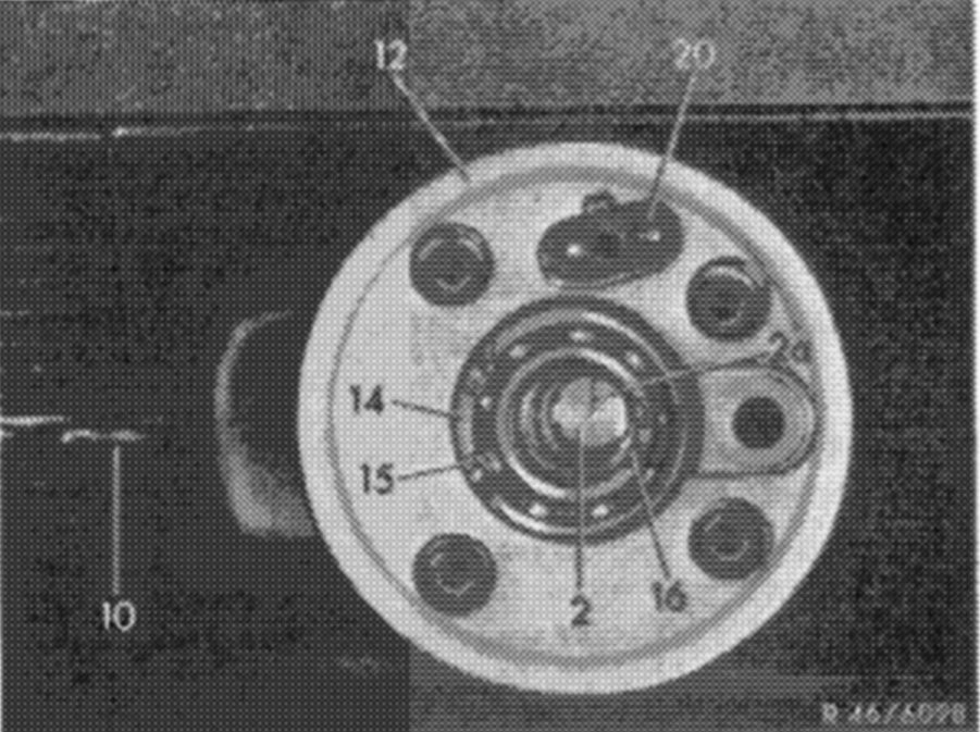
2 Steering shaft
3 Hex. nut with spring washer
5 Jacket tube
10 Combination switch
11 Rubber cover
12 Bearing body
13 Needle bearing
14 Radial ball bearing
15 Locking ring
16 Slip ring
17 Locking ring
6. Remove locking ring for radial ball bearing from steering shaft and knock steering shaft out of bearing body in downward direction by means of a plastic hammer.
Checkup
7. Check radial ball bearing for wear and replace, if required
8. Check telescopic connection of steering shaft. Steering shaft should telescope in axial direction only at approx. 800 N (80 kp).
Check length of steering shaft and adjust. For this purpose, attach an old steering coupling to steering shaft and adjust steering shaft to required dimension by means of light blows with a plastic hammer.
9. Check needle bearing (13) in bearing body (12) and replace needle bearing, if required.
Installation
Note:
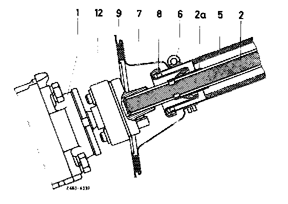
Beginning 1978, a modified steering shaft (2nd version) together with the steering wheel valid for model 123 and a modified jacket tube will be installed. Note that the steering shaft 1st version should not be installed into a jacket tube 2nd version. The reversed installation steering shaft 2nd version into a jacket tube 1st version - is permitted, but the steering wheel should then also be replaced due to the changed hub dia. During insertion into steering coupling, the steering shaft should not be axially displaced. In addition, make sure that the sleeve (8) is not damaged or pushed away from jacket tube.
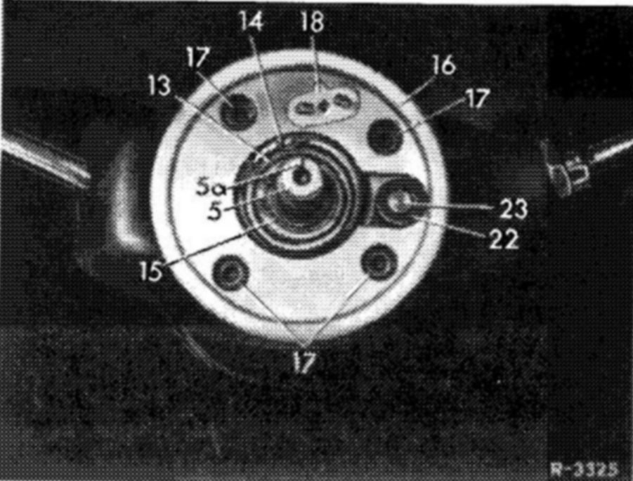
10. Introduce steering shaft (5) including bearing body (16) into jacket tube and steering coupling. Make sure that the wheels are in straight-ahead position and that the restoring cam for the combination switch is in center of cutout on jacket tube. In addition, the notch (5a) on steering shaft should point upwards.
11. Attach bearing body (16) to jacket tube by means of hex. socket screws (17).
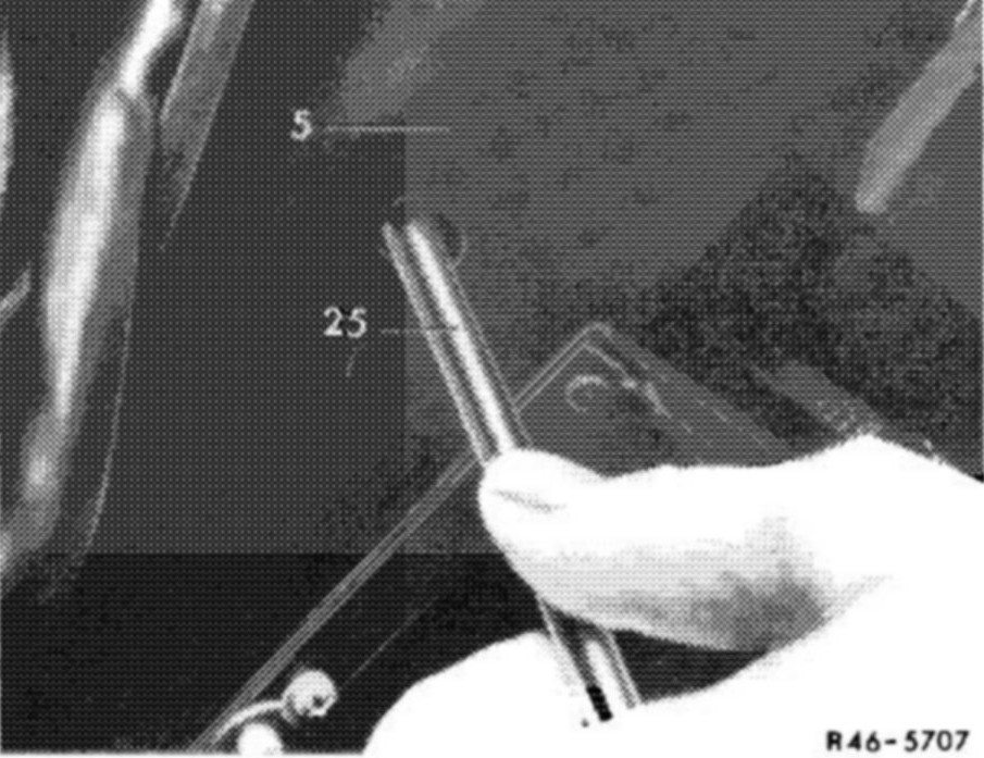
12. Check longitudinal adjustment of steering shaft 1st version through bore in jacket tube (5). For this purpose, insert assembly pin (25) in check bore of steering shaft.
The assembly pin should easily enter check bore. (Steering shaft 2nd version has no check bore).
Note:
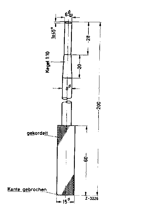
The assembly pin is self-made according to specified dimensions.
13. Screw upper hex. socket screw (13) into steering coupling (12) and tighten. Tightening torque 25 Nm (2.5 kpm) reference value.
14. Install steering wheel.
15. Check steering lock for function.
16. Connect cable of carbon brush to combination switch, install combination switch and check for function. Insert rubber cover into jacket tube.