Procedures
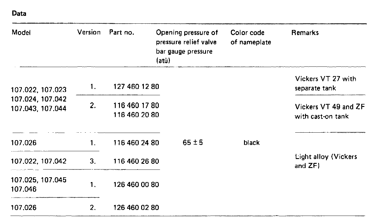
REMOVE AND INSTALL POWER STEERING PUMPData:
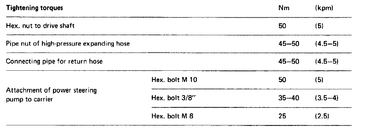
Tightening Torques:
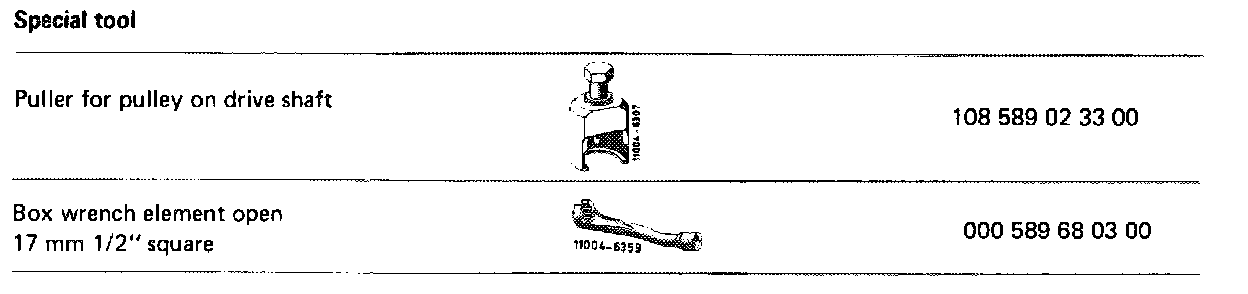
Special Tools:
Removal
All Models
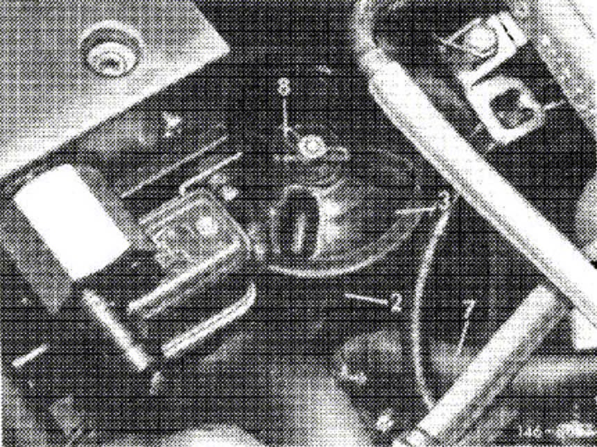
1. Unscrew knurled nut or wing nut (8) from supply tank (2) Remove closing cover (3), pressure spring and steadying plate. Draw oil from supply tank with a syringe.
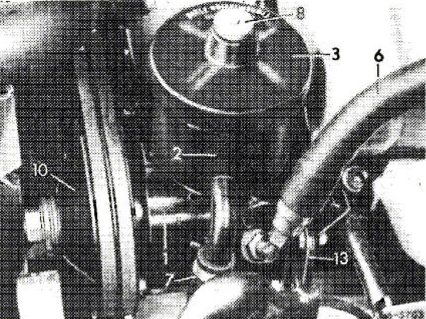
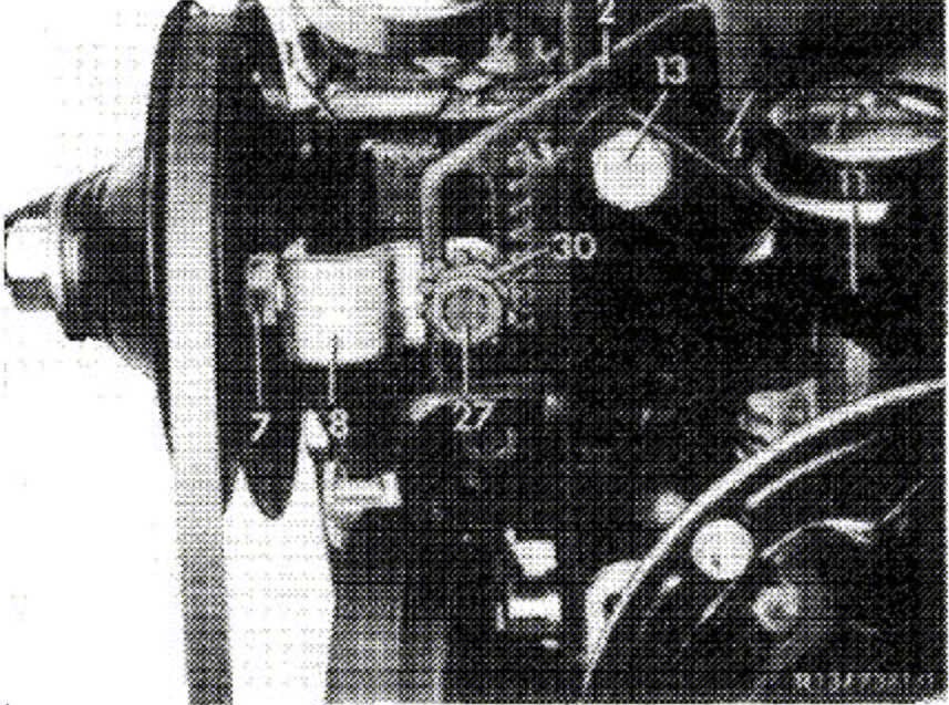
Layout of Vickers power steering pump VT 27 in models 107.022 and 107.042.
2. Loosen high-pressure expanding hose (6) and return hose (7) on power steering pump, close connections on pump and hoses with blind plugs.
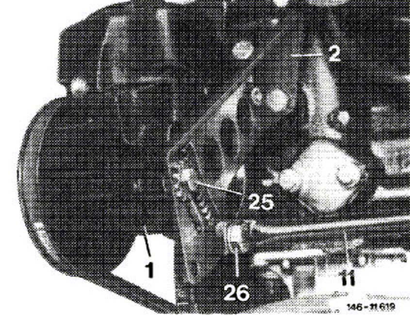
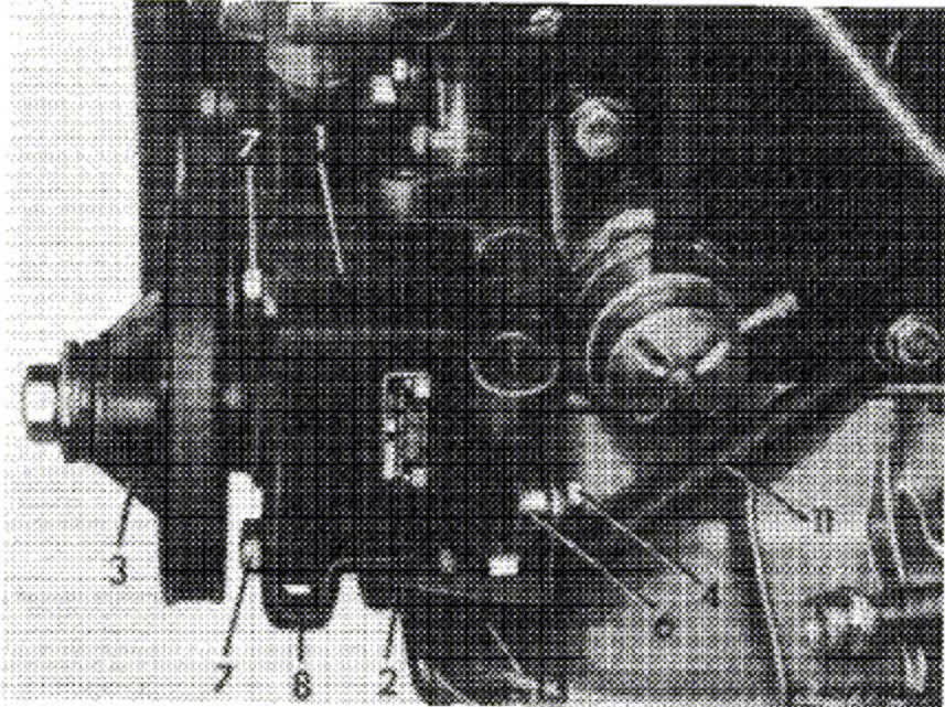
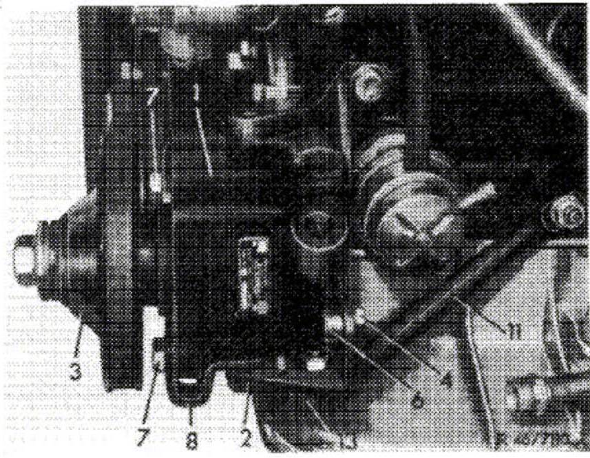
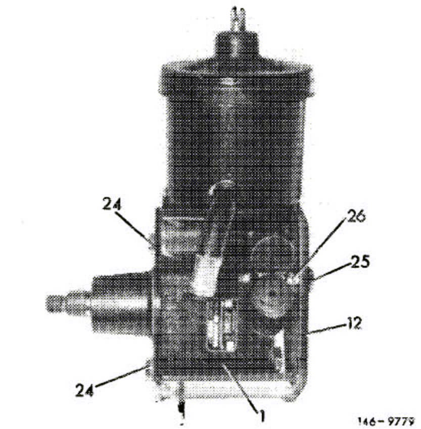
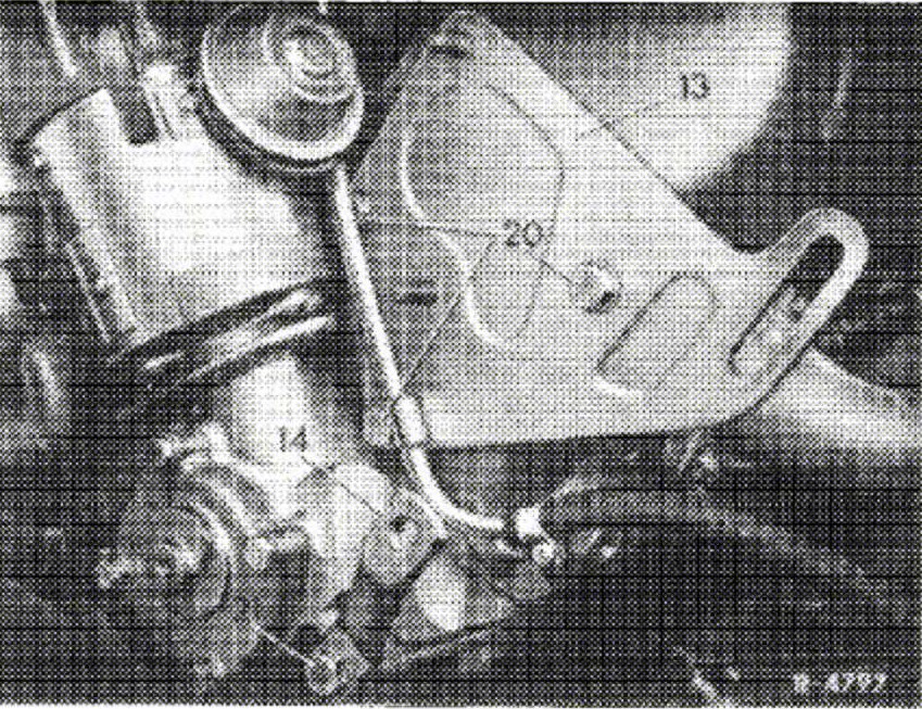
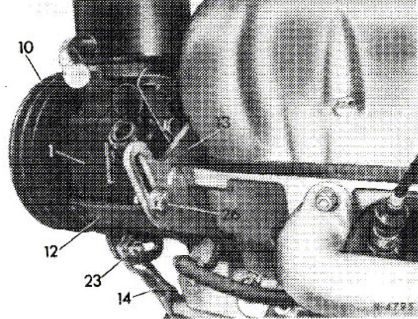
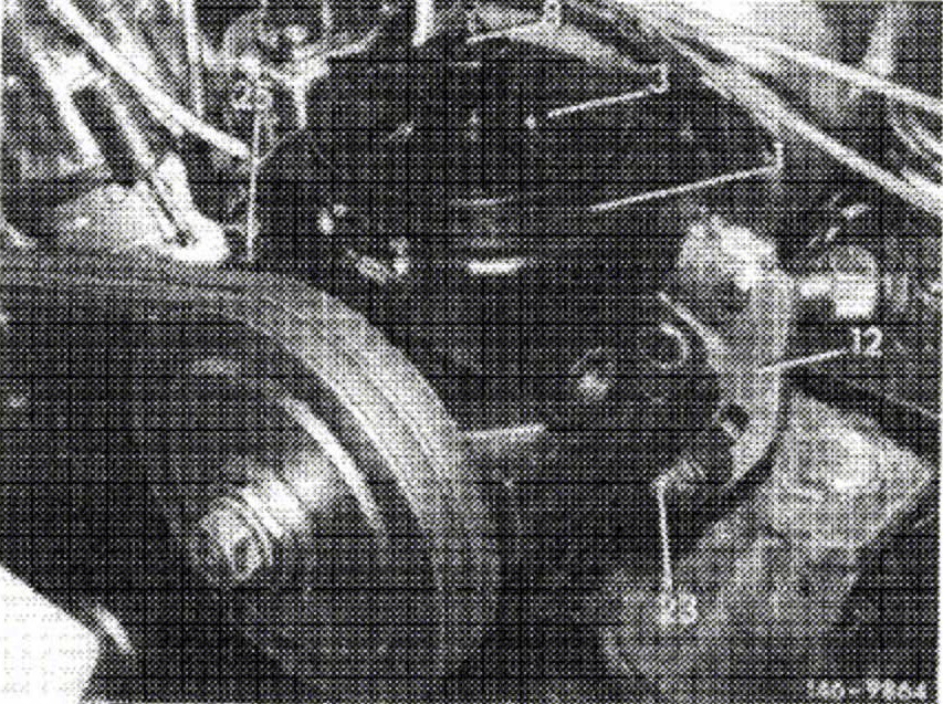
Layout of Vickers power steering pump VT 27 in models 107.023, 107.024, 107.043, 107.044.
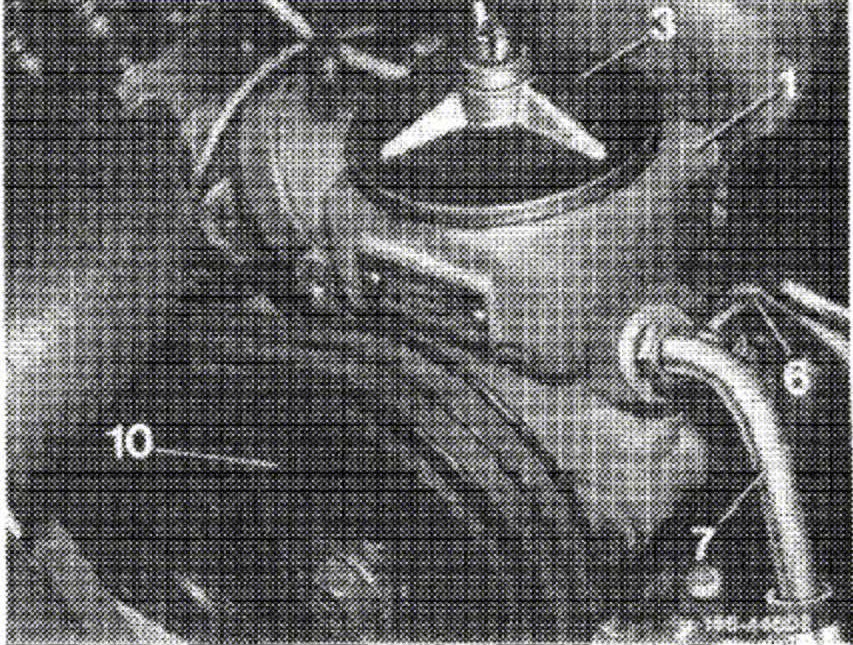
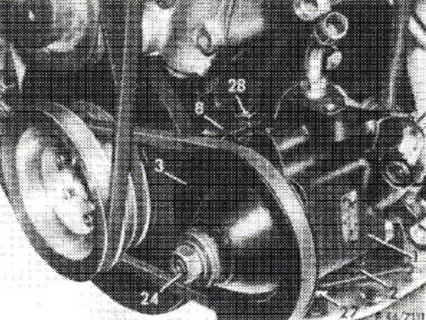
Layout of Vickers VT 49 and ZF power steering pump in models 107.022 and 107.042.
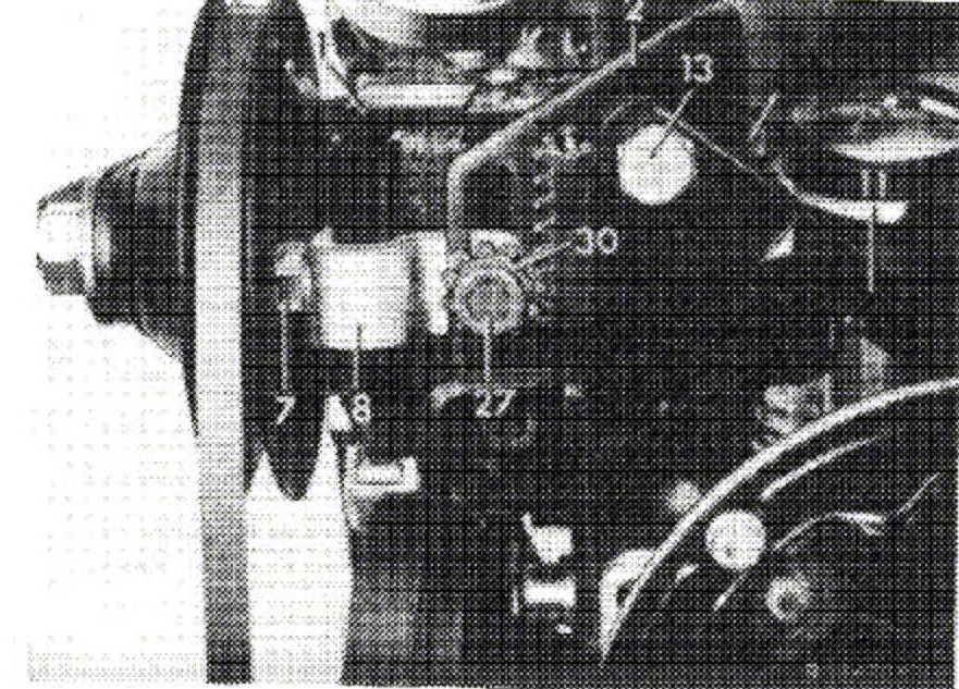
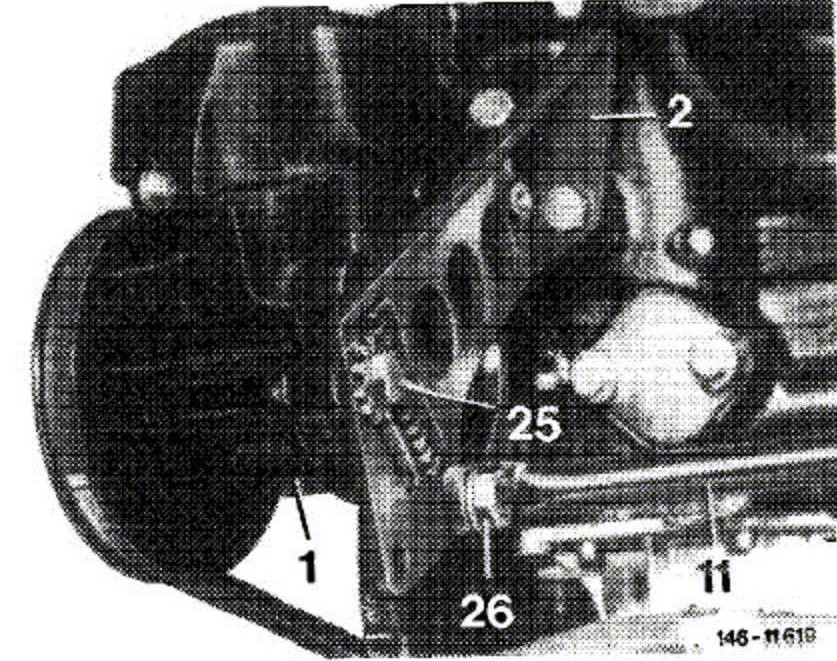
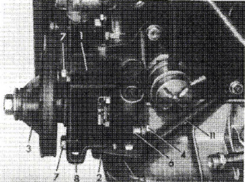
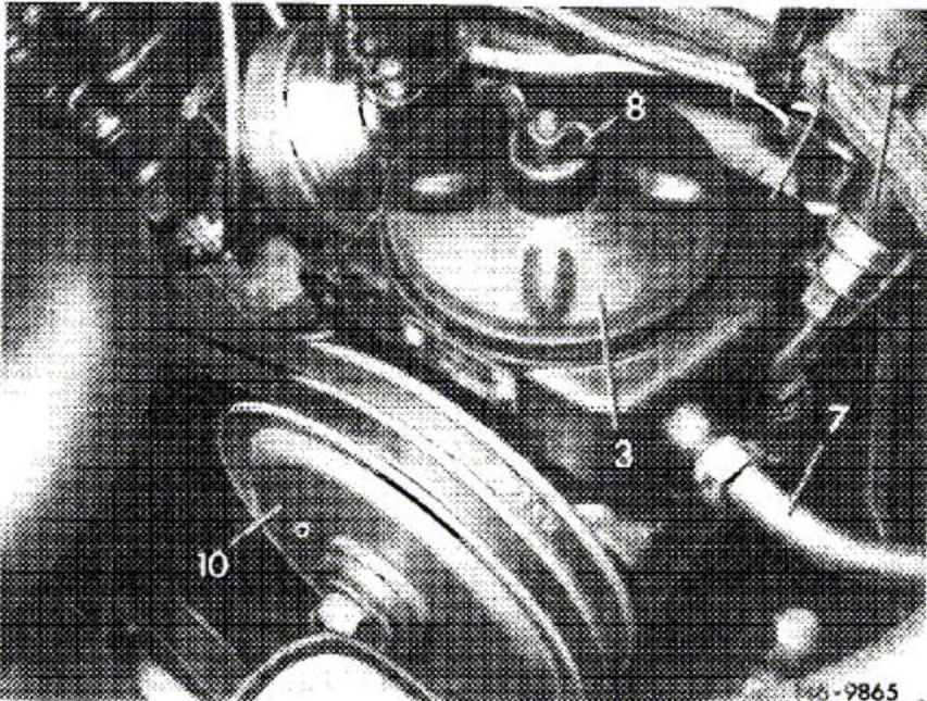
Layout of Vickers VT 49 and ZF power steering pump in models 107.023, 107.024, 107.025, 107.026, 107.043, 107.044, 107.045, 107.046.
Models 107.022 and 107.042 with Vickers VT 27 power steering pump
3. Loosen radiator shell.
4. Loosen hex. socket screw (27) as well as hex. screws (4).
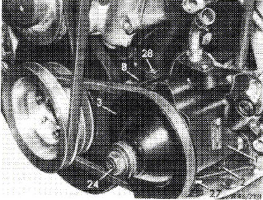
5. Loosen hex. socket screw (28).
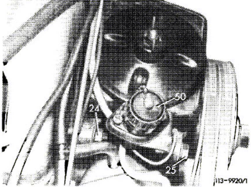
6. Unscrew hex. nut (24) from drive shaft and force off pulley with puller. Push power steering pump toward crankcase by turning gear wheel and remove vee-belt.
7. Unscrew hex. screws (4) and (7) and remove power steering pump.
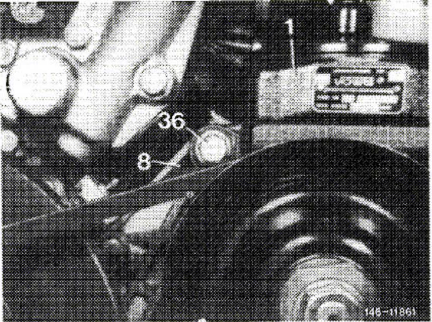
Models 107.023, 107.024, 107.043 and 107.044 with Vickers VT 27 power steering pump
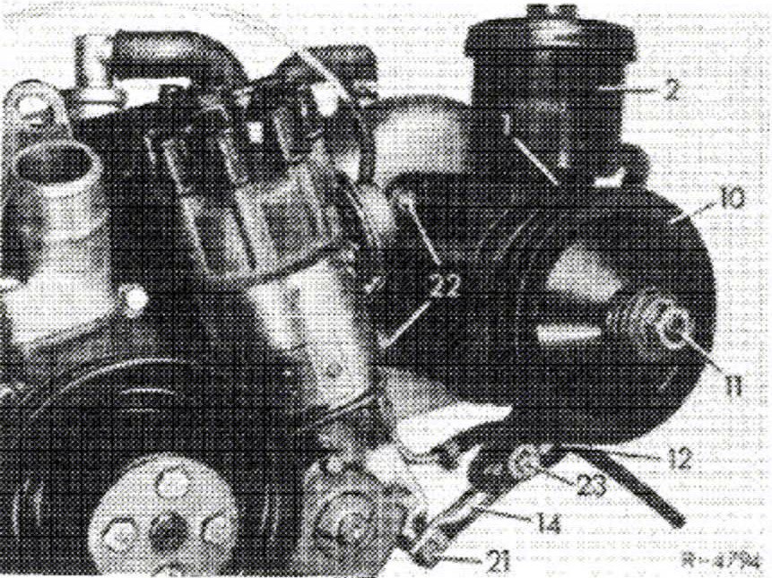
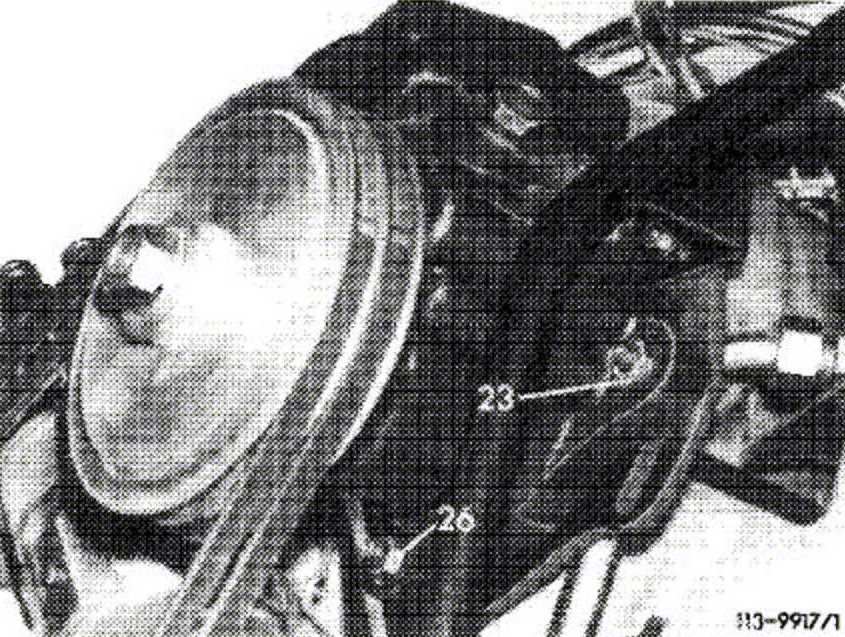
8. Loosen hex. nuts (22) at fastening plate and hex. screw (23) on support (14). Push power steering pump toward engine and take both vee-belts from pulley (10).
9. Unscrew hex. screws and nuts and remove power steering pump including carrier.
10. Unscrew hex. nut from drive shaft while applying counterhold at flats (36 mm) of pulley.
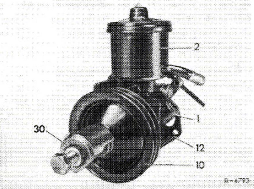
11. Remove pulley (10) from drive shaft with puller (30).
Note:
Remove pulley only with puller 108 589 02 33 00, since otherwise the power steering pump will be damaged.
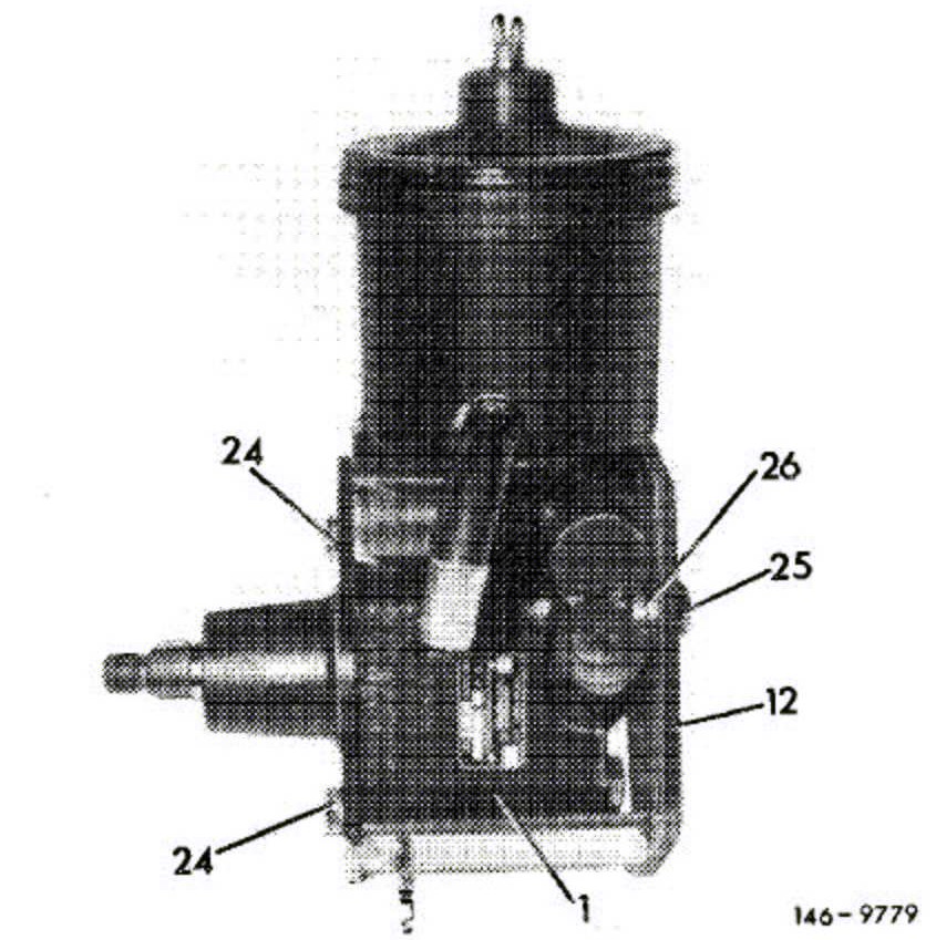
12. Unscrew hex. socket screws (24) (7 mm hex. socket) and hex. screw (25) (inch threads) and remove power steering pump from carrier (12), while paying attention to spacing sleeve (26).
Models 107.022 and 107.042 with Vickers VT 49 and ZF power steering pump
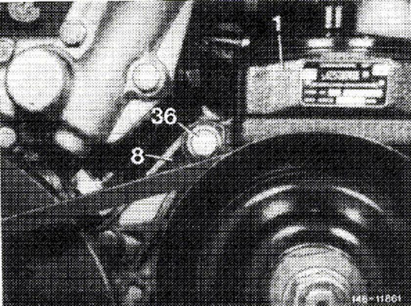
13. Loosen hex. screw (36).
14. Loosen hex. nut on adjusting screw (25), then slacken vee-belt by turning adjusting screw. Remove vee-belt from pulley.
15. Unscrew hex. screw (36) and hex. nut at adjusting screw, remove power steering pump.
16. Unscrew hex. nut from drive shaft and remove pulley with puller.
Note:
Remove pulley only with puller 108 589 02 33 00, since otherwise the power steering pump will be damaged.
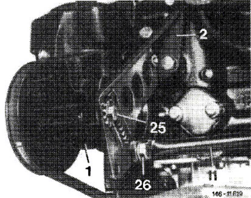
Models 107.023, 107.024, 107.025, 107.026, 107.043, 107.044, 107.045 and 107.046 with Vickers VT 49 and ZF power steering pump
17. Remove diagnosis plug (5) from power steering pump.
18. Loosen hex. nut (24).
19. Loosen hex. nut (26) and (23).
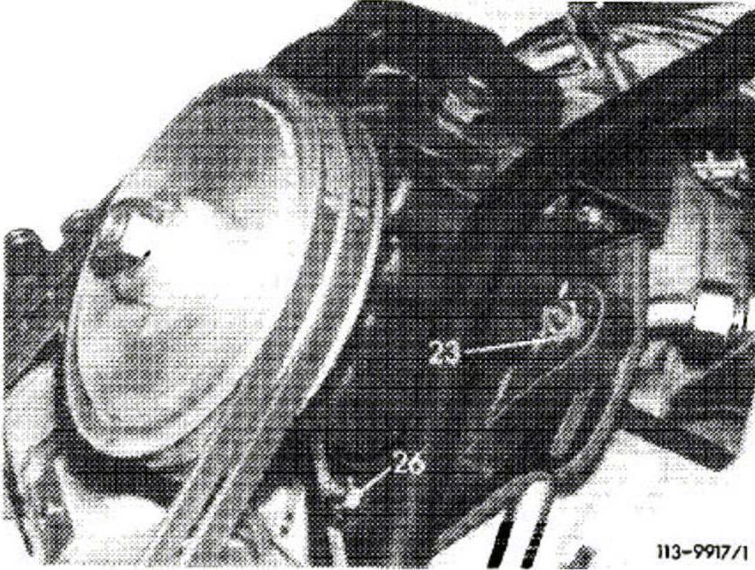
20. Swivel power steering pump toward engine by means of tensioning screw (23) and remove vee-belt from pulley.
21. Unscrew hex. nut (23, 25 and 26) and remove power steering pump.
22. Unscrew hex. nut from drive shaft.
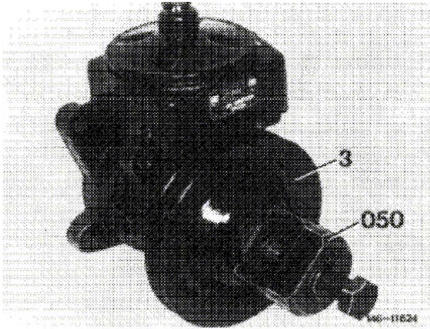
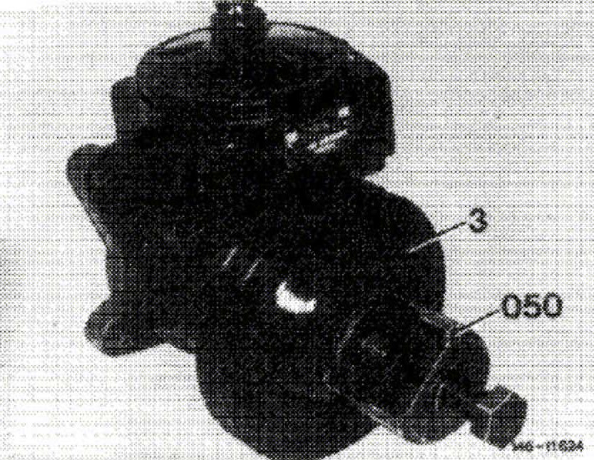
23. Remove pulley (3) from drive shaft with puller (050).
Note:
Remove pulley only with puller 108 589 02 33 00, since otherwise the power steering pump will be damaged.
Installation
Note:
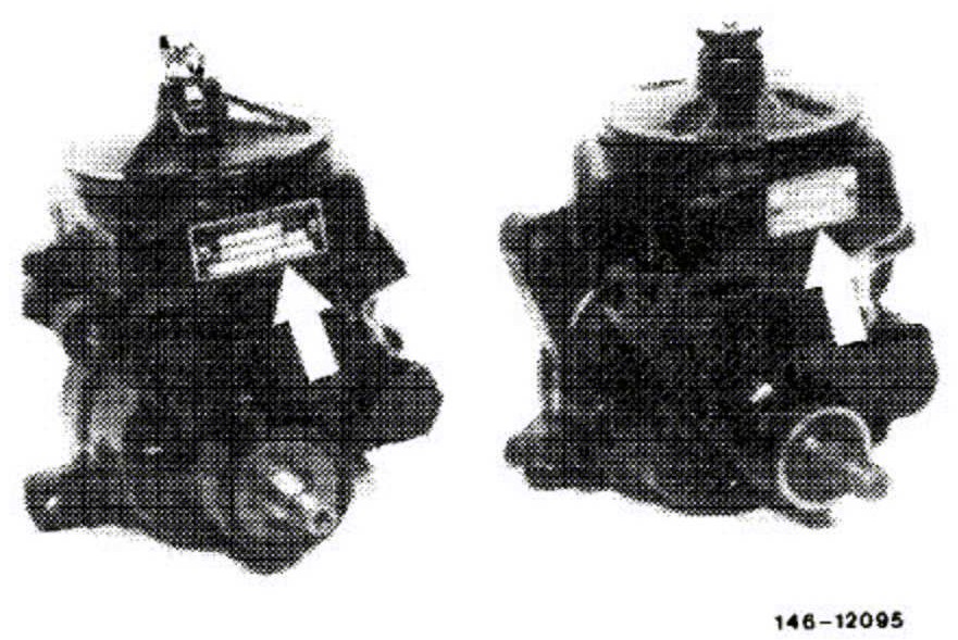
Make sure that a power steering pump is installed on which the pressure relief valve will open at 65 bar (atu) The opening pressure is punched into type rating plate of pump. In addition, the type rating plate has a black basic color.
Models 107.022 and 107.042 with Vickers VT 27 power steering pump
24. Screw hex. screws (7) into pump housing and tighten to 65 to 70 Nm (6.5 to 7 kpm).
25. Place spacing sleeve (6) between pump and carrier and screw-in hex. screw (4), but do not yet tighten.
26. Attach pulley to drive shaft and tighten hex. nut 50 Nm (5 kpm), while applying counterhold to flats on pulley.
27. Mount vee-belt. Push power steering pump from crankcase by means of gear wheel until the correct belt tension is attained. Then tighten hex. socket screws (27) and (28).
28. Tighten hex. screw (4).
Types 107.023, 107.024, 107.043 and 107~044 with Vickers VT 27 power steering pump
29. Insert power steering pump into carrier (12) and attach with hex. screws. The rear screw (25) has inch threads.
30. Attach pulley to drive shaft making sure that the cone of the drive shaft and the flange on the pulley are free of grease. Tighten hex. nut to 50 Nm (5 kpm).
31. Retighten hex. screws (20) for attaching plate (13) to cylinder head.
32. Attach power steering pump including carrier (12) to fastening plate (13) and to support. But do not yet tighten hex. screws or nuts.
Place both vee-belts on pulley (10). Tension vee-belt and tighten hex. screws or nuts.
Types 107.022 and 107.042 with Vickers VT 49 and ZF power steering pump
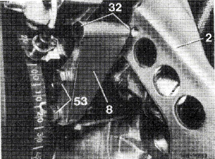
33. Check plastic bushings (32) in holder, renew bushings, if required.
34. Attach pump in holder (8) or carrier with hex. screw (36), but do not yet tighten.
35. Screw hex. nut on adjusting screw (25). Place vee-belt on pulley. Tension vee-belt with adjusting screw. Tighten hex. screw and hex. nut at adjusting screw.
Models 107.023, 107.024, 107.025, 107.026, 107.043, 107.044, 107.045 and 107.046 with Vickers VT 49 and ZF power steering pump.
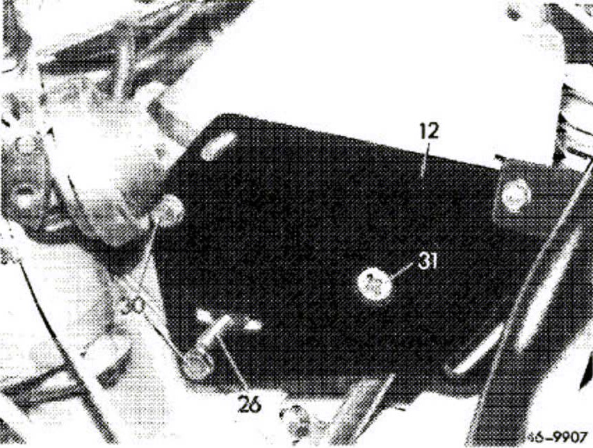
36. Retighten hex. screws (30) and Phillips screw (31) for attaching plate (12) to cylinder head.
37. Attach power steering pump with hex. nuts and hex. screws (23 and 26) to fastening plate, but do not yet tighten hex. nuts and hex. screws.
38. Attach power steering pump with hex. nuts and hex. screws (23, 25 and 26) to fastening plate, but do not yet tighten hex. nuts and hex. screws.
39. Attach pulley to drive shaft, mount vee-belt and tension Tighten hex. nuts.
All Models
40. Connect high.pressure expansion hose and return hose to pump housing. Pay attention to perfect in stallation of hose.
41. Fill servo.system with specified oil, add oil up to mark with the engine running.
42. Turn steering several times to full lock left and right to bleed system.
43. Check oil level and servo-system for leaks.