Compressor Shaft Seal: Service and Repair
Sectional View of Shaft Seal and Seat of Seal
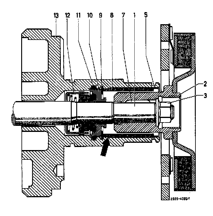
1 Shaft
2 Hub
3 Collar nut
4 Locking ring
5 Holding ring
6 Spacing washer
7 Woodruff key
8 Felt ring
9 Locking ring
10 Ceramic ring
11 0-ring
12 Shaft seal
13 Front head member
Removal
1 Remove spring plate. Service and Repair
Note: Removal of pulley and clutch coupler is not necessary for removal and installation of shaft seal.
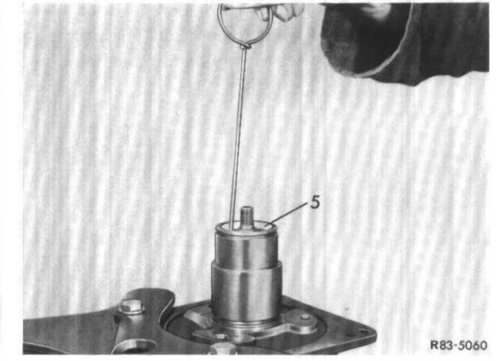
2 Remove holding ring (5) and felt ring (8).
Note: Puller is self-made from 2.5 mm dia. brass wire.
5 Holding ring
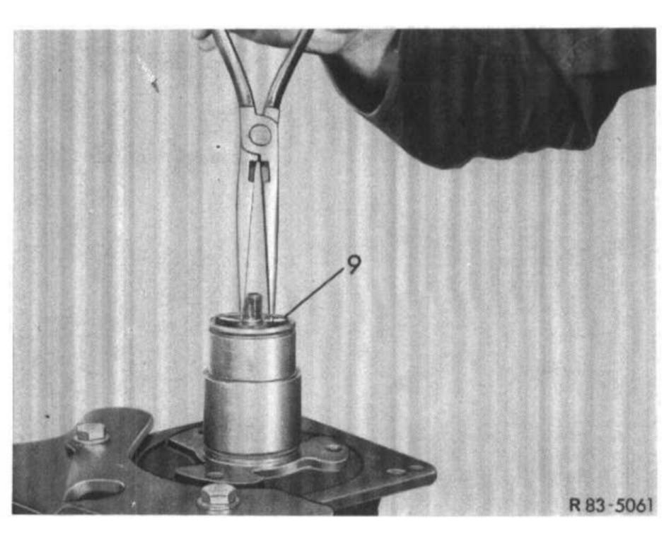
3 Remove locking ring (9) for shaft seal.
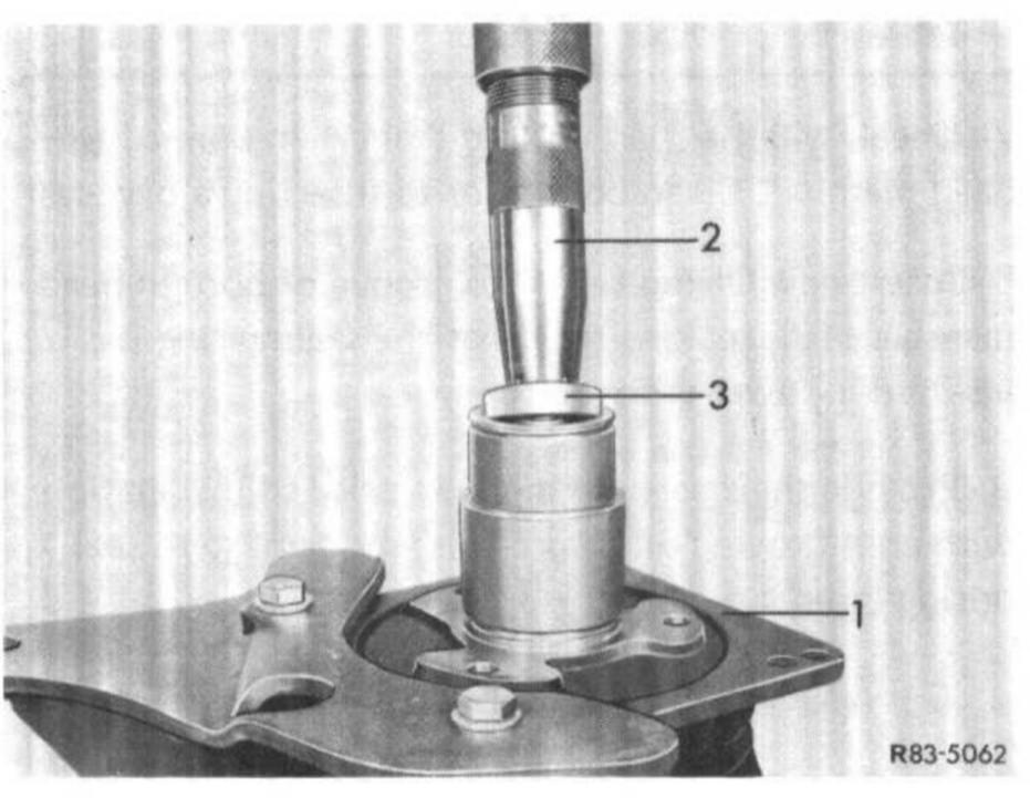
4 Remove slip ring (3 or 9) with assistance of remover and installer (2).
1 Refrigerant compressor
2 Remover and installer
3 Slip ring
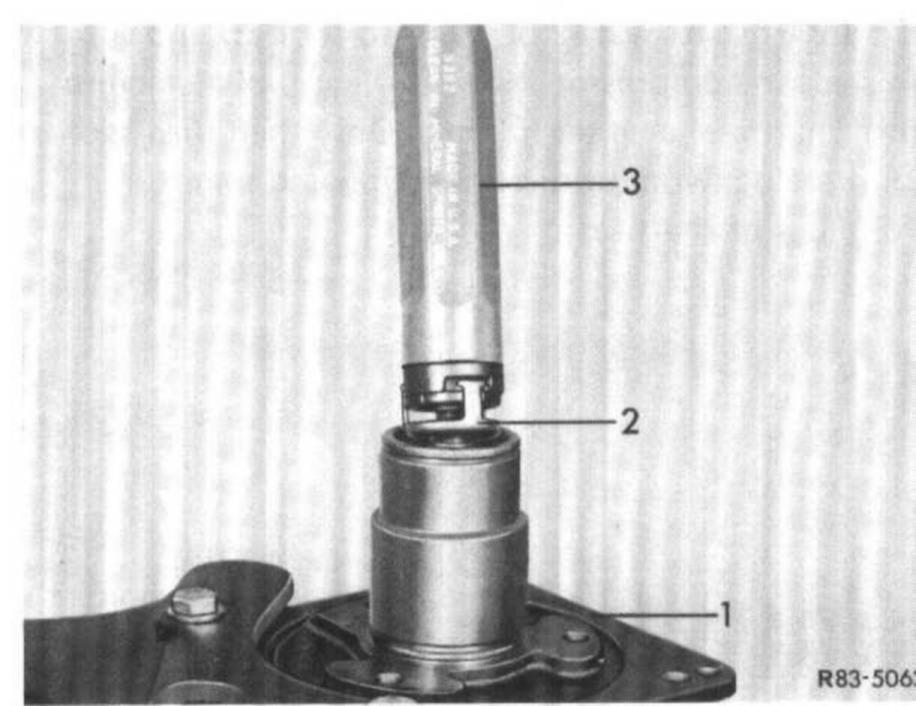
5 Remove shaft seal (2 or 11) with the assistance of tool (3). For this purpose, push on tool, turn tool clockwise to grip the lugs of the shaft seal with the locking tongues on tool. Remove complete shaft seal by pulling straight from shaft.
1 Refrigerant compressor
2 Shaft seal
3 Remover and installer
6 Remove 0-ring (11) from inside bore in front head member of refrigerant compressor. This can be done by means of a piece of wire bent into a hook.
Installation
7 Check whether parts of old seal are in bore of front head member. Clean bore prior to inserting a new seal.
8 Insert new 0-ring (11) into groove of bore in head member (13), making sure that the sealing ring is inserted in lower groove.
9 Provide shaft sealing ring (11) prior to installation with cold-flowing oil to prevent any damage to seal during insertion.
10 Insert shaft seal (2 or 12) into tool (3) and slip on shaft in compressor. Keep turning tool clockwise until shaft seal engages in shaft. Only then turn tool counterclockwise for disconnection and removal from lugs of shaft seal.
1 Refrigerant compressor
2 Shaft seal
3 Remover and installer
11 Introduce slip ring (3 or 10) with assistance of tool (2) into bore of front head member until ring touches shaft seal. Make sure that the 0-ring (11) is not pushed out of groove.
1 Refrigerant compressor
2 Remover and installer
3 Slip ring
Attention! Protect sealing surface of slip ring against any damage, such as scratches.
12 Introduce locking ring (9) with flat side down into bore until locking ring rests on slip ring. Then push against locking ring by means of locking ring pliers or a screwdriver until locking ring snaps into groove.
Note: The shoulder (refer to arrow) seen from end of bore is a projection and not a groove.
13 Install spring plate as described in step a. Service and Repair
14 Check oil level in refrigerant compressor.
15 Check compressor for leaks.