Removal and Installation of Electromagnetic Clutch
Tightening Torque
Flange nut to shaft 20 Nm
Special Tools
Pin spanner for counterholding spring plate 116 589 10 07 00.
Pulling tool for spring plate 000 589 07 35 00.
Installing tool for spring plate 000 589 49 43 00.
Puller 000 589 88 33 00.
Thrust piece for puller 116 589 05 63 00.
Mandrel for pulley 115 589 02 35 02.
Remover and installer for slip ring 000 589 21 61 00.
Remover and installer for shaft sealing ring 000 589 65 63 00.
Holding device for refrigerant compressor 109 589 00 31 00.
Note: Removal and installation of spring plate with pulley and clutch coupler, as well as of shaft seal, can be performed without removal of refrigerant compressor and refrigerant compressor carrier.
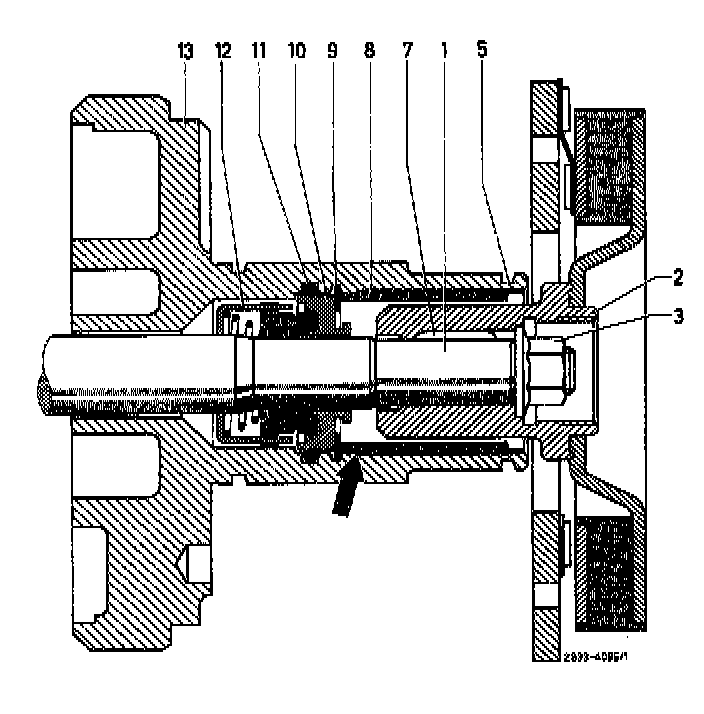
Sectional View of Shaft Seal and Seat of Seal
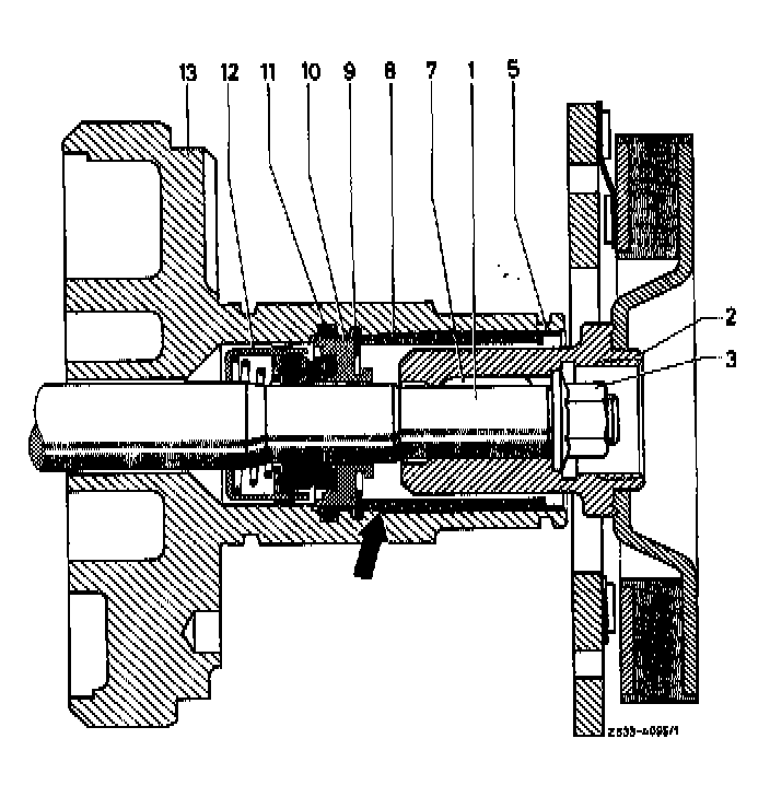
1 Shaft
2 Hub
3 Collar nut
4 Locking ring
5 Holding ring
6 Spacing washer
7 Woodruff key
8 Felt ring
9 Locking ring
10 Ceramic ring
11 0-ring
12 Shaft seal
13 Front head member
a) SPRING PLATE
Removal
1 If the refrigerant compressor is removed, clamp refrigerant compressor with refrigerant compressor carrier into vise, without refrigerant compressor carrier into holding fixture for refrigerant compressor.
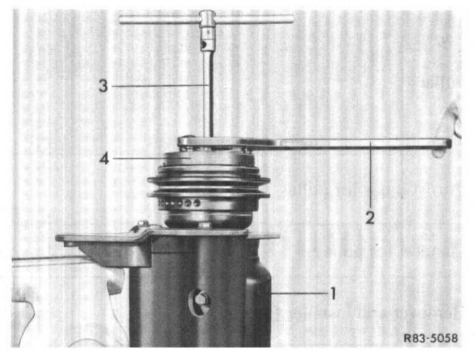
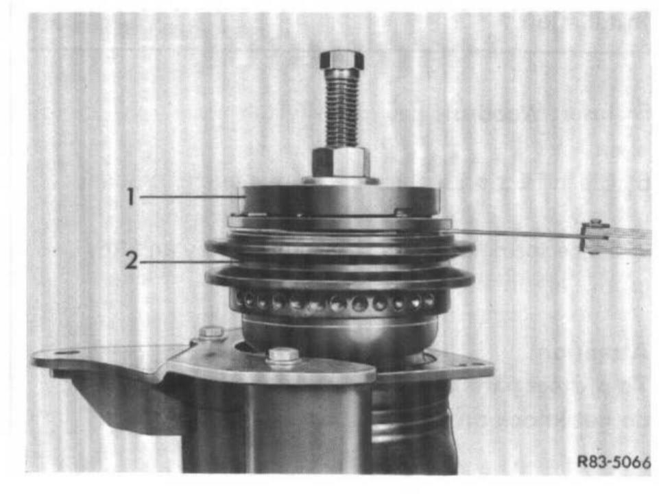
2 Prevent rotation of spring plate (4) by means of holding tool (2), unscrew collar nut from shaft using 14 mm socket.
1 Refrigerant compressor
2 Holding tool
3 Socket
4 Spring plate
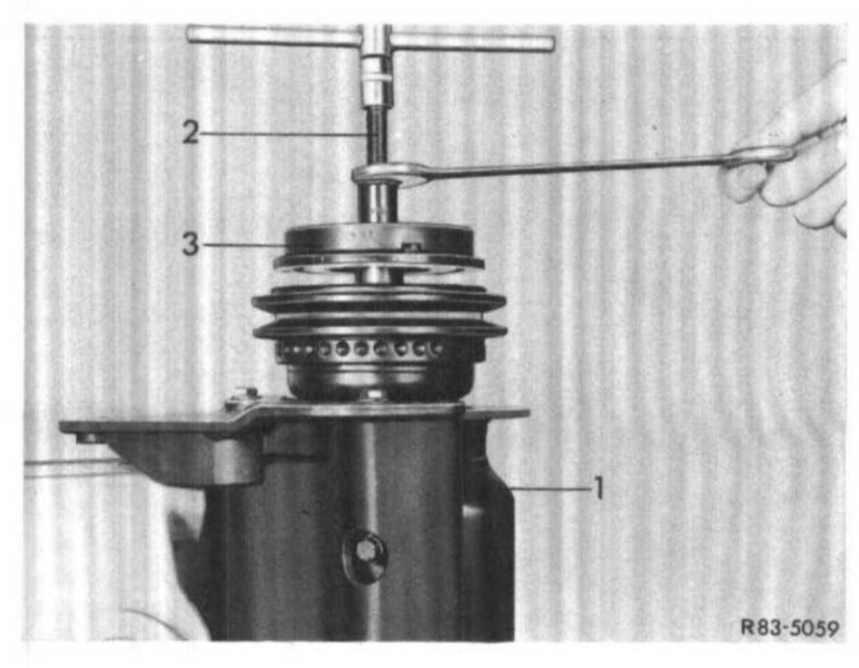
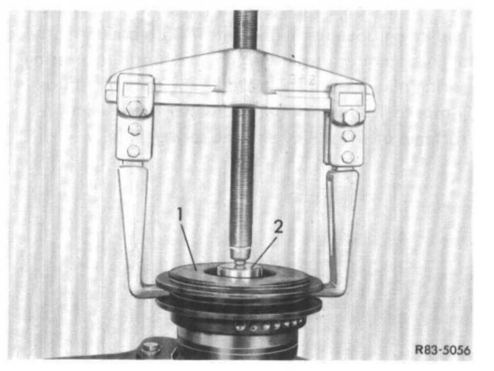
3 Screw remover (2) into hub. Hold tool in place with wrench and tighten central screw.
1 Refrigerant compressor
2 Remover
3 Spring plate
4 Remove Woodruff key from shaft.
Installation
5 Insert Woodruff key into shaft.
6 Clean friction surface of spring plate and pulley.
7 Place spring plate on shaft so that key and key groove are in alignment.
Attention! To protect parts inside compressor against damage, do not knock on or against spring plate or shaft.
8 Place spacer (2) on spring plate (1). Insert installer (3) through spacer (2) and screw installer (3) to shaft end.
9 Hold hexagon of tool in position and screw-in center screw by several turns to press spring plate in part on shaft.
10 Remove installer (3) and spacer (2), check key and key groove for alignment. If both are correctly aligned, mount installer again and continue pressing spring plate (1) on shaft until a distance of approx. 1 mm to 1.5 mm is obtained between the friction surfaces of the pulley and the spring plate.
11 Remove installer (3) and spacer (2).
12 Screw on new collar nut. Hold spring plate in place with holding tool (2) and tighten counternut. Distance between the two friction surfaces of the pulley and the spring plate should now amount to approx. 0.5 to 1.5 mm.
1 Spring plate
2 Pulley
b) PULLEY
Removal
1 Remove spring plate (see step a).
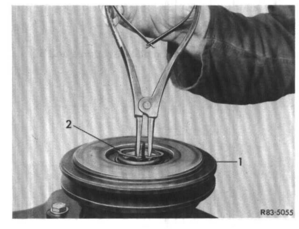
2 Remove locking ring (2) and holding ring (5).
1 Pulley
2 Locking ring
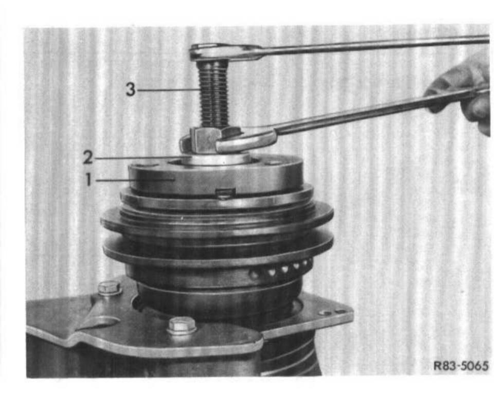
3 Insert guide piece (2) into bore in head member of compressor.
1 Pulley
2 Guide piece
4 Pull-off pulley (1) with puller (3).
Installation
5 If the same pulley is reinstalled, clean friction surface of pulley. If friction surface is damaged, e.g. by overheating, replace pulley together with spring plate.
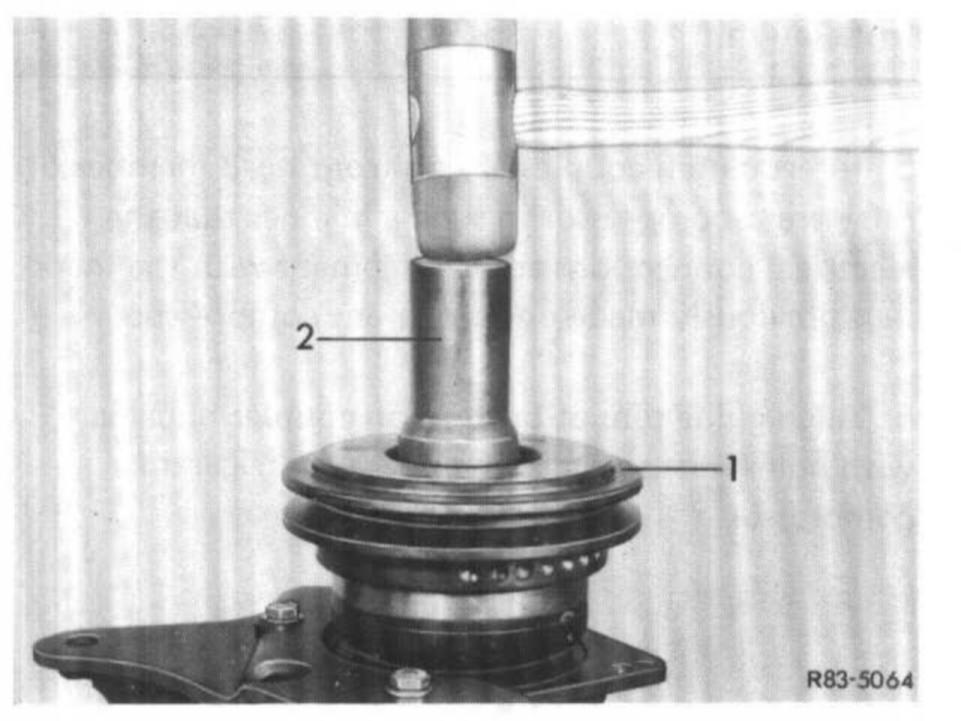
6 Knock pulley (1) with the assistance of punch (2) onto guide journal of refrigerant compressor. Position punch in such a manner that the impact force is guided against inner bearing race and the bearing itself is not damaged.
1 Pulley
2 Punch
7 Check pulley for unobstructed operation. Then insert locking ring (2) with flat side down.
1 Pulley
2 Locking ring
8 Install spring plate (see step a).
c) CLUTCH COUPLER
Removal
1 Remove spring plate and pulley (see steps a and b).
2 Mark position of electric connections on coupler housing on front head member of refrigerant compressor.
3 Remove locking ring (3).
4 Lift clutch coupler (2) from refrigerant compressor (1).
1 Refrigerant compressor
2 Clutch coupler
3 Locking ring
Installation
5 Insert clutch coupler (2) on front head member of refrigerant compressor in such a manner that the electrical connections are in alignment with the markings previously made on refrigerant compressor.
6 Align guide pins at bottom on coupler housing with holes in front head member of refrigerant compressor.
7 Install locking ring (3) with flat side of ring in direction of coupler.
8 Install pulley and spring plate (see steps a and b).
d) SHAFT SEAL OF REFRIGERANT COMPRESSOR
Sectional View of Shaft seal and Seat of Seal
1 Shaft
2 Hub
3 Collar nut
4 Locking ring
5 Holding ring
6 Spacing washer
7 Woodruff key
8 Felt ring
9 Locking ring
10 Ceramic ring
11 0-ring
12 Shaft seal
13 Front head member
Removal
1 Remove spring plate (see a).
Note: Removal of pulley and clutch coupler is not necessary for removal and installation of shaft seal.
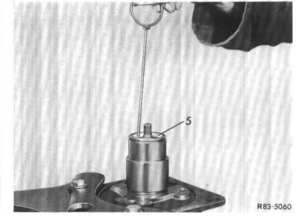
2 Remove holding ring (5) and felt ring (8).
Note: Puller is self-made from 2.5 mm dia. brass wire.
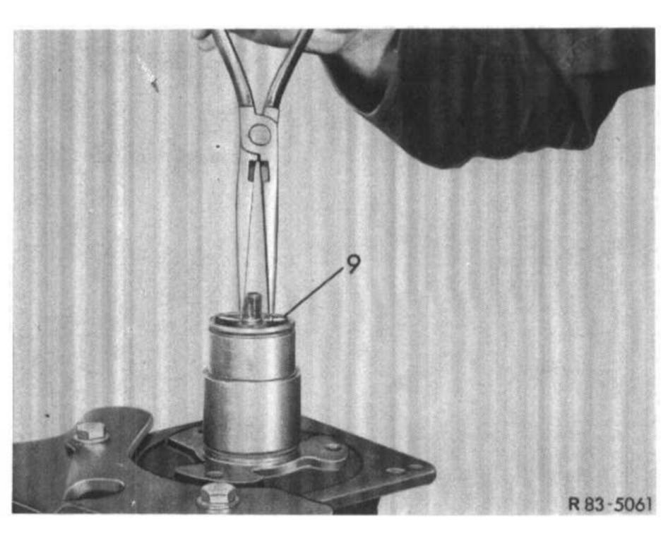
3 Remove locking ring (9) for shaft seal.
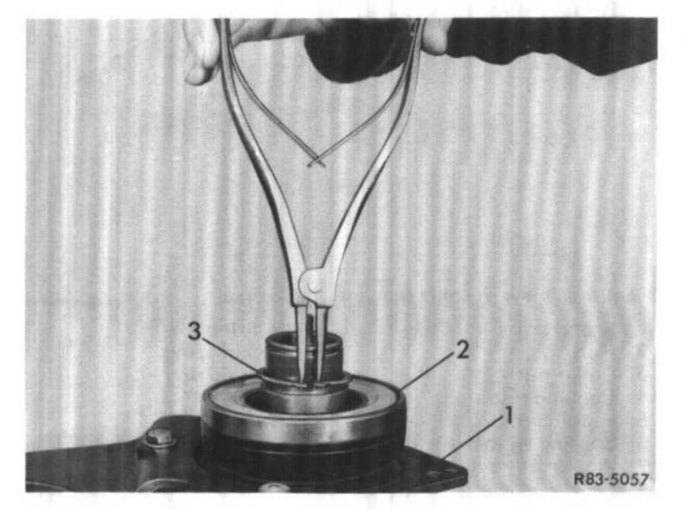
4 Remove slip ring (3 or 9) with assistance of remover and installer (2).
1 Refrigerant compressor
2 Remover and installer
3 Slip ring
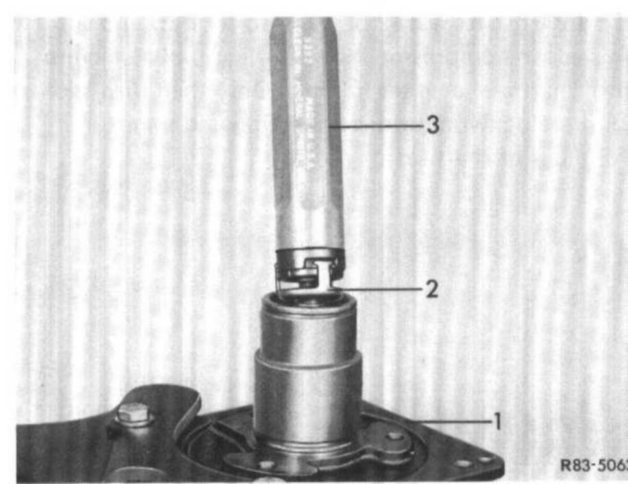
5 Remove shaft seal (2 or 11) with the assistance of tool (3). For this purpose, push on tool, turn tool clockwise to grip the lugs of the shaft seal with the locking tongues on tool. Remove complete shaft seal by pulling straight from shaft.
1 Refrigerant compressor
2 Shaft seal
3 Remover and installer
6 Remove 0-ring (11) from inside bore in front head member of refrigerant compressor. This can be done by means of a piece of wire bent into a hook.
Installation
7 Check whether parts of old seal are in bore of front head member. Clean bore prior to inserting a new seal.
8 Insert new 0-ring (11) into groove of bore in head member (13), making sure that the sealing ring is inserted in lower groove.
9 Provide shaft sealing ring (11) prior to installation with cold-flowing oil to prevent any damage to seal during insertion.
10 Insert shaft seal (2 or 12) into tool (3) and slip on shaft in compressor. Keep turning tool clockwise until shaft seal engages in shaft. Only then turn tool counterclockwise for disconnection and removal from lugs of shaft seal.
1 Refrigerant compressor
2 Shaft seal
3 Remover and installer
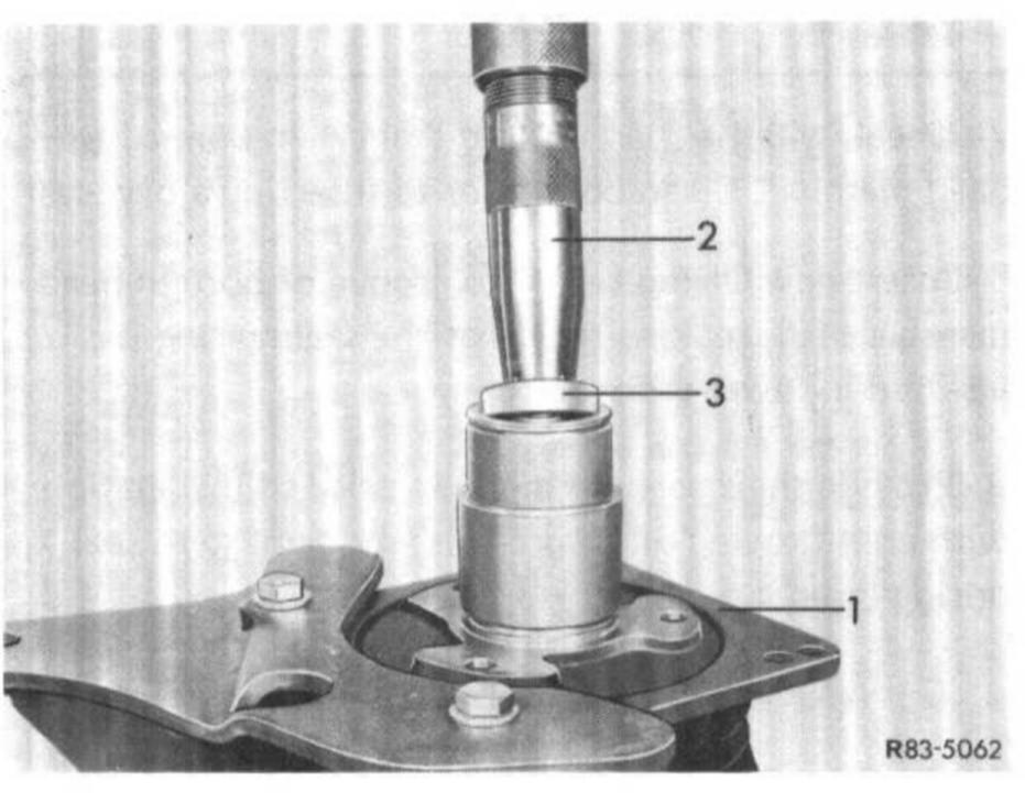
11 Introduce slip ring (3 or 10) with assistance of tool (2) into bore of front head member until ring touches shaft seal. Make sure that the 0-ring (11) is not pushed out of groove.
1 Refrigerant compressor
2 Remover and installer
3 Slip ring
Attention! Protect sealing surface of slip ring against any damage, such as scratches.
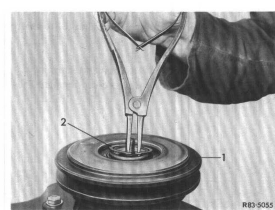
12 Introduce locking ring (9) with flat side down into bore until locking ring rests on slip ring. Then push against locking ring by means of locking ring pliers or a screwdriver until locking ring snaps into groove.
Note: The shoulder (refer to arrow) seen from end of bore is a projection and not a groove.
13 Install spring plate as described in step a.
14 Check oil level in refrigerant compressor.
15 Check compressor for leaks.