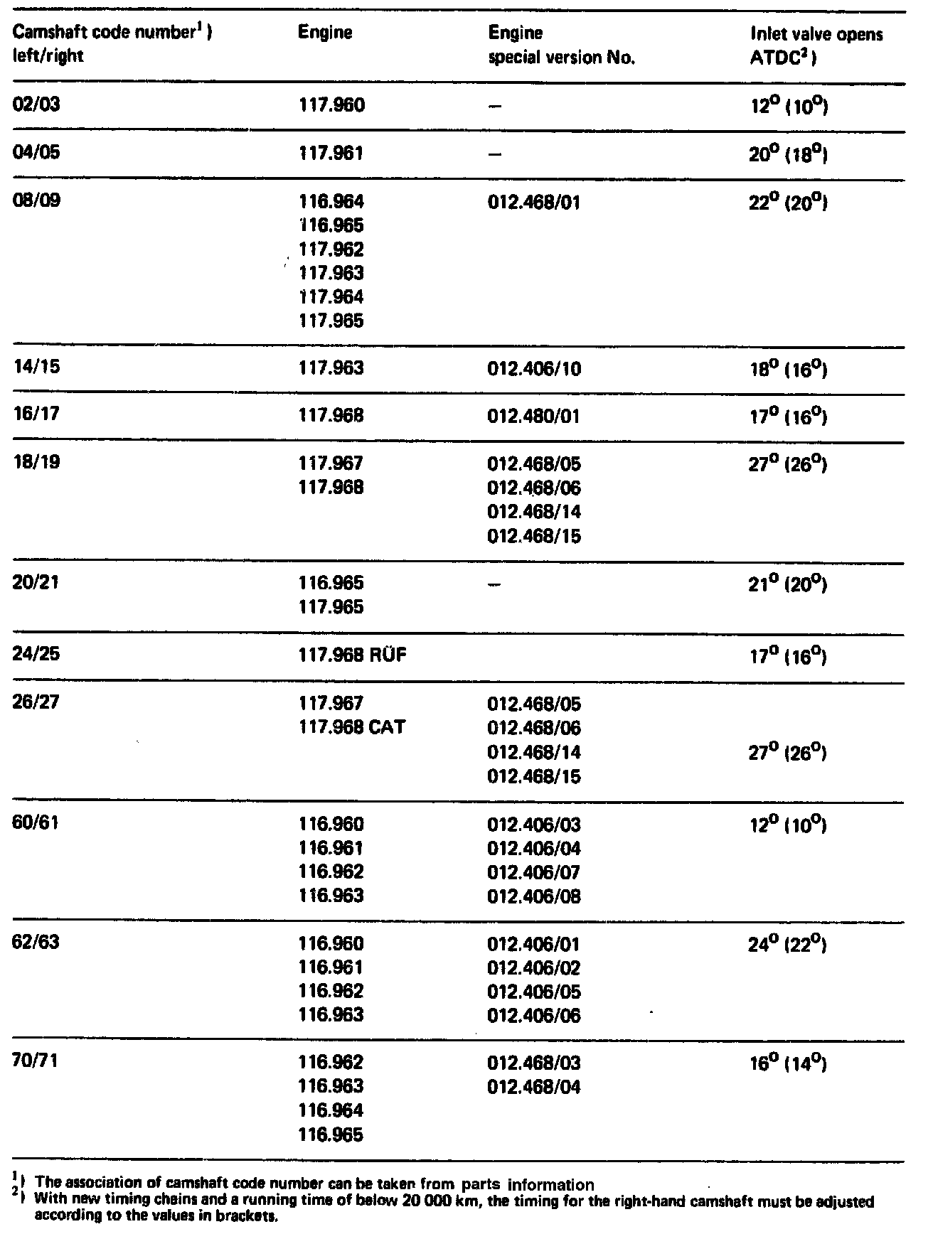
Camshaft: Adjustments
Timing in degree - crank angle, with 2 mm valve lift:
NOTE: During assembly jobs it is sufficient if the marks on the camshafts coincide at ignition TDC position of 1st cylinder.
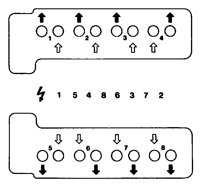
Check "intake valve opens" on 1st and 6th cylinder at 2 mm valve lift.
NOTE: The timing chain is secured against turning on the crankshaft sprocket once the oil sump is installed.
Checking:
1 Check camshaft code number on rear end of camshafts.
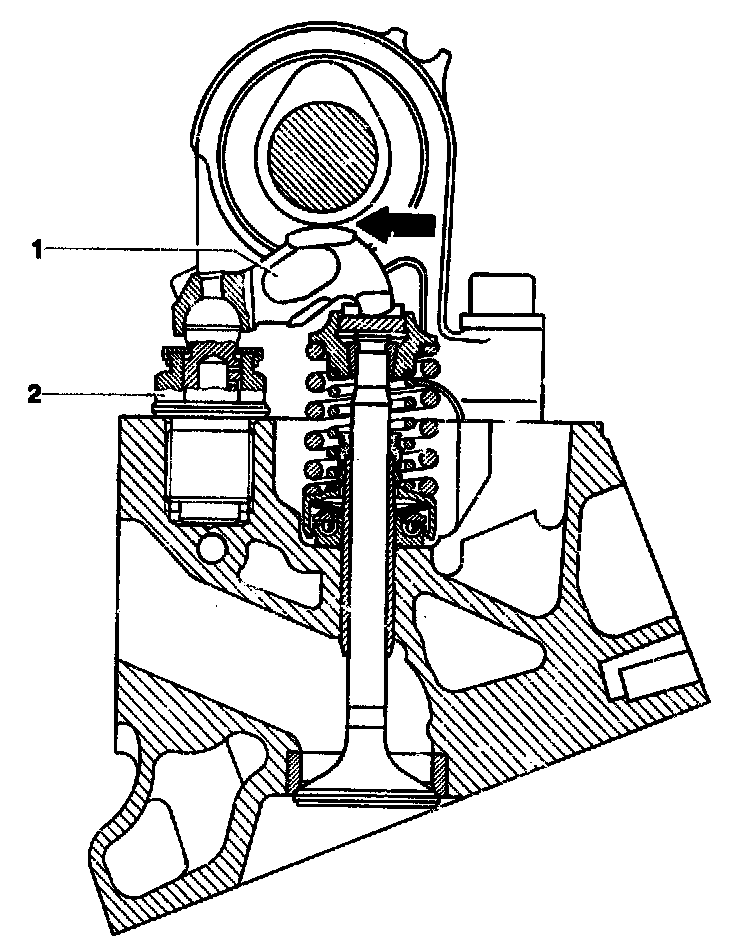
2 Remove rocker arm (1) and valve clearance compensating elements (2) on intake valve of 1st and 6th cylinder. Install valve adjusting screw (1), part No. 116 050 11 20, on intake valve of 1st and 6th cylinder instead of compensating elements (2). Install rocker arm.
CAUTION: The rocker arms and the valve clearance compensating elements should be installed in the place from which they were removed.
3 Rotate crankshaft (27 mm socket) until the cam tip rests against intake valve of 1st cylinder in upward position.
Rotate crankshaft in engine direction of rotation only.
4 Turn valve adjusting screw until rocker arm rests free of play against camshaft heel (arrow).
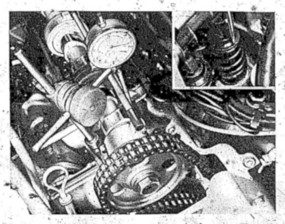
5 Attach dial gauge holder to cylinder head.
6 Clamp dial gauge with extension pin in dial gauge holder with a preload of 3 mm.
The measuring pin should rest on the valve spring retainer in an accurately vertical position.
7 Set the large pointer to 0.
8 Rotate crankshaft until the pointers of the dial gauge return by 2 mm to a preload of 1 mm. The valve lift will then be 2 mm.
9 In this engine position the value on the vibration damper should be in agreement with the value,, Intake valve opens" in the table.
10 Perform this test on the intake valve of 6th cylinder by repeating figures 4 to 9.
Adjusting
If the timing must be corrected, install an offset Woodruff key or if the chain has been elongated too much. a new timing chain.
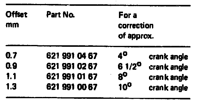
Woodruff keys are available as indicated in the above image.
An offset by one tooth on the camshaft sprocket results in approx. 18 ° on the crankshaft.
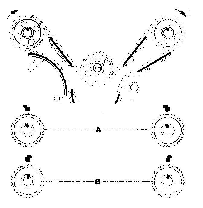
Referring to the above image, installation position A results in earlier commencement of opening.
Installation position B results in later commencement of opening.
An offset of the Woodruff key to the right (in the direction of driving) results in an earlier commencement of opening, while an offset to the left results in a later commencement of opening.
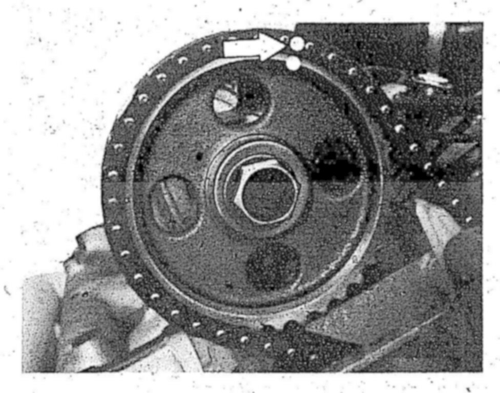
11 Mark camshaft sprockets and timing chain relative to each other (arrow).
12 Remove the respective camshaft sprocket.
13 Place a rag under the camshaft and remove the Woodruff key.
14 Insert the selected Woodruff key.
15 Install the camshaft sprocket while paying attention to the color coding.
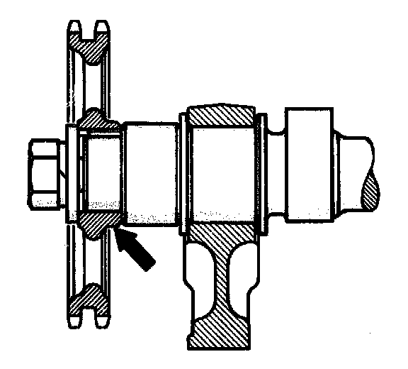
The wide collar on the camshaft sprocket should face to the camshaft (arrow).
Do not tighten the bolt.
16 Repeat items 4 to 9.
17 Tighten bolt to 100 Nm.
18 Check basic position of hydraulic valve clearance compensating elements and correct. Service and Repair
19 Complete the engine.